Today will be a big push to finish the Rotax installation, however I an not in too much of a hurry not to get it done right. So let's get started.
Reference: Page 46-17 of the RV-12 airplane plans
Step 1: Fabricate FF-1222 Manifold Pressure Hose from EA HOSE H173 rubber 15 inches long.
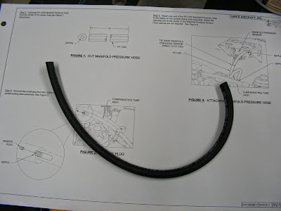
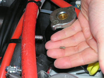
Step 2: Remove the small plug from the nipple on compensating tube assembly.
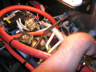
Step 3: Attach one end of the FF-1222 Manifold Pressure Hose to the nipple on the compensating tube assembly. Attach the opposite end to the nipple on the Manifold Pressure Sensor. Hose clamps are not required.
This completes page 46-17.
Reference: page 46-18
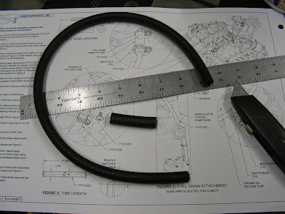
Step 1: Cut FF-01224 Interconnect Hose and FF-01225 Drain Hose from EA HOSE H175 per Figure 1 dimensions.
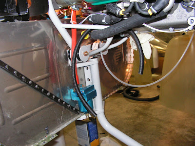
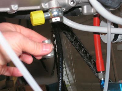
Step 2: Slip FF-01224 Interconnect Hose over fuel pump drain fitting and secure using hose clamp called out in Figure 2 on page 46-18 of the RV-12 plans.
Step 3: Place cushioned clamps onto engine oil return tubes as shown in Figure 2. Close clamps using safety wire (not shown) to aid installation.
Step 4: Install but delay attachment of FF-01225 Drain Hose. Starting from beneath aft cylinder route hose between two coolant hoses (lower coolant hose not shown) then downward and parallel to Gascolator to Fuel Pump Hose as shown in Figure 2.
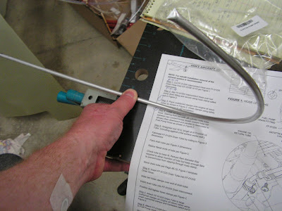
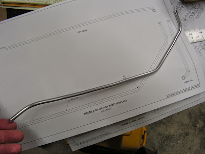
Step 5: Straighten out 18 in. length of ATO-032X1/4 Tube. (Unrolling against a flat surface works well.) Fabricate FF-01223 Drain Tube by cutting to Figure 3 dimensions. Flare drain tube per Figure 3 dimensions. Radius flared ends of tube per Figure 3. Check tube to hose fit. Reduce flare diameter if/as required to allow insertion of tube but keep enough flare to prevent tube from slipping through hose clamp. Bend drain tube per Page 46-19, Figure 1 template.
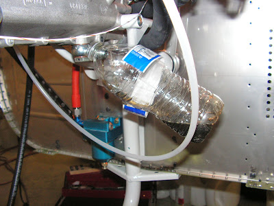
Step 6: Insert FF-01223 Drain Tube into FF-01225 Drain Hose. Slide two hose clamps over end of drain tube. Insert drain tube into FF-01224 Drain Interconnect. Position and tighten hose clamps per Figure 2.
The last three steps on this page will be completed next entry.
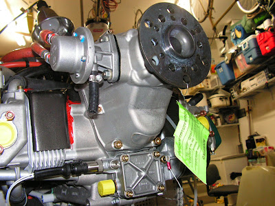
Reference: Page 46-20.
NOTE: The instructions on page 46-20vapply to engines received with the banjo style hose nipple. If the straight Adaptor/Fluid Fitting is already installed, disregard these instructions.
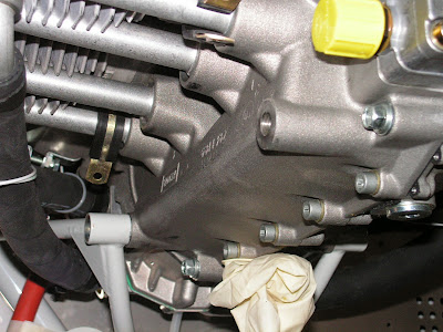
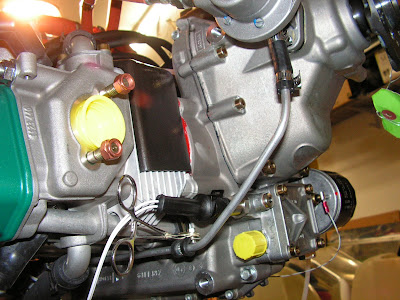
Step 1: Remove the Banjo Bolt M16X1.5X28 940 879, Hose Nipple 16 956 050 (banjo fitting) and Gasket 430 622 washers from the bottom aft of the engine as shown in Figure 1. In this application one of the removed gaskets/washers may be reused for the straight fitting.
NOTE: Use loctite on the threads of the fitting per manufacturer's instructions. Loctite 243 works best for this application (Loctite 242 will work if Loctite 243 is unavailable). Dry torque values are for non-oily threads. Dry Torque values are preferred if oil can be removed from case threads. If there is residual oil (threads are shiny in appearance) reduce torque value down ("wet torque") to 15 ft lbs, or 180 inch lbs [20NM] from 19 ft lbs [25NM].
Builder's note: It hard to have dry threads with oil dripping out ot the engine!
Step 2: Apply loctite and install the Adaptor 956 651 straight fluid fitting with Gasket 430 622 as shown in Figure 1.

This completes page 46-20 and today's work on the RV-12. The next work session will finish up the installation of the Rotax 912.

