Today starts the installation of the Rotax onto the RV-12 airplane. It's a shift from working with sheet metal and fiberglass. Torque values specified by Rotax supersede all values listed in this section by Van's Aircraft. Torque values must be strictly followed. Have torque wrenches calibrated before use.
Reference: page 46-02
Step 1: Set the engine on a steady work surface at a convenient working height and take pictures of the systems and components at various angles for your own reference later. Continue taking pictures after removing parts that conceal other components.

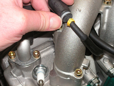
Step 2: Check the water inlet elbow clocking. If necessary remove, reposition and reinstall the elbow as shown.

Builder's note: The picture above is as the Rotax was received, so the water inlet need to be clocked as shown below.

Step 3: Mark the ignition harness electrical connectors for modules A1, B1, A2 and B2.

Step 4: Remove the retaining screw from the small clamp at the rear of the ignition module and pull the harness free.

Step 5: Remove the A & B electrical connectors from the metal mounting bracket by gently prying the tab at the shielded harness end toward the connector and slide them off the bracket.
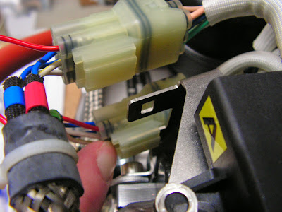
Step 6: Separate the two connector halves of the A & B connectors by gently prying the single tab and then pulling them apart. CAUTION: Do not pry the tabs opposite each other on the connector. Do not reconnect these connectors until directed to do so later in this section.


Step 7: Disconnect all eight spark plug leads from the spark plugs with a firm tug. Pull the lower harness as far up between the cylinders as possible. See arrow in Figure 5. CAUTION: Leads do not detach from ignition coils.
Step 8: Remove the two cushioned clamps and spacer by removing the allen screw from the inboard crank trigger coil.

This completes page 46-02
Reference: Page 46-03
Step 1: Discard the small clamp, allen screw and spacer. Reattach the large clamp and wire harness with the hardware called out in Figure 1 on page 46-03 of the RV-12 plans. Torque the allen screw to 55 in-lbs.


NOTE: When checking the trigger coil gap measure between the trigger coil and the trigger cam on the flywheel not the plastic ignition cover.
Step 2: Check for proper trigger coil clearance. The gap should be .012-.016. See Figure 2 arrow. For more information see the ROTAX 912 AND 914 SERIES MAINTENANCE MANUAL (HEAVY MAINTENANCE). Search using keywords: trigger coil gap (with clamps). If the gap needs to be adjusted it will be necessary to rotate the crankshaft. For directions on how to rotate the crankshaft see Step 3, otherwise skip to Step 5.
Builder's note: I removed the plastic cover to make checking the clearance easier. While the gaps on my engine didn't need adjusting, I still need to rotate the engine over to align the trigger with the coils.
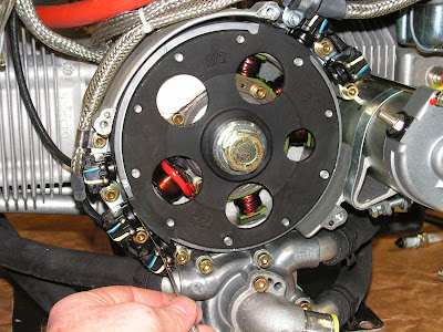
NOTE: There are two trigger cams approximately 180 degrees apart and each aligns with only one of the coils on the flywheel. The crankshaft must be rotated in order to align the trigger cams with the coils on the flywheel. Removing one spark plug per cylinder will make rotating the crankshaft much easier.
Step 3: Insert two large bolts in holes clocked 180 degrees apart in the propeller flange. Place a large screwdriver or other lever between the bolts and slowly rotate the crankshaft.

Step 4: Temporarily install the spark plugs. Thread them in a few turns. They will be removed again in the Spinner and Propeller Section.
Step 5: Remove the ignition module by removing the forward left-side mounting bolt. Remove the retaining nut from the bottom of the rubber isolator several inches aft and below the mounting bolt location.


NOTE: Carburetors and compensating tube remain attached to the intake manifolds, and fuel lines remain attached until later in the engine installation.
Step 6: Remove the eight screws attaching the intake manifolds. Lift the manifolds, ignition module and attached components up and flip them forward over the gearbox to allow access to the top of the engine case. Rest everything on a cardboard box (or similar) to prevent straining the hoses and ignition leads. Verify that each cylinder intake port still has its O-ring seal in place.
WARNING: Prevent foreign objects from entering the cylinder intake port holes by covering the ports with masking tape.


This completes page 45-03 and this entry. That's all for today's work on the RV-12 Rotax engine.

