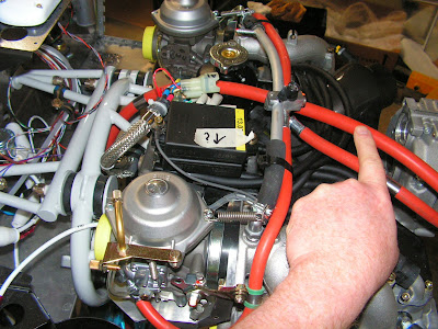
Today continues with the installation of the Rotax engine on the RV-12 airplane. The engine is already hung and now starts the running of the various hoses and wiring.
Step 1: Route the attached Gascolator to Fuel Pump Hose beneath the clamp block. See Figure 1. Slip the Gascolator to Fuel Pump Hose beneath the WD-1220 Engine Mount Ring and to the left of the starter. Pass the hose through the triangular shaped support of the engine mount ring. Connect the end of the hose to the elbow on the gascolator.

WARNING: It is possible to install the VA-216 Fuel Return Assy. with the ends reversed which will result in low fuel pressure. DOUBLE CHECK TO VERIFY A PROPER INSTALLATION.
Step 2: Confirm that the VA-216 Fuel Return Assy. was properly manufactured. Since there is no way to visually inspect the banjo fitting orientation use the following technique. Blow air into the end of the hose so that it comes out the banjo fitting. It should be more difficult to blow air through the brass fitting side (the orifice side of the banjo fitting) than through the steel fitting side. Position the VA-216 Fuel Return Assy. so that the brass fitting is oriented to the right side of the engine.
NOTE: When loosening or tightening the banjo bolts support the clamp block (fuel manifold) appropriately.
Step 3: Attach the VA-216 Fuel Return Assy. to the clamp block using the Rotax hardware called out in Figure 2. See Figure 3 for completed assembly. Torque banjo bolt to 90 in-lbs.
Step 4: Attach the VA-216 Fuel Return Assy. to the union bulkhead fitting on the F-1201B Firewall Shelf. See Figure 4.
Step 5: Tie-wrap the VA-216 Fuel Return Assy. to the left carburetor and compensating tube.

Step 6: Attach the VA-216 Fuel Return Assy. to the elbow coming from the bottom of the fuel pressure sensor.

Reference: 46-12
Step 1: Identify the portion of the WH-RV12-IGNITION Wiring Harness that has the outer insulation removed to expose a length of shielding. The end closest to this will connect to the electrical connectors A1 and B1 at the ignition module.

NOTE: The A1 and B1 electrical connector plugs should still be disconnected from their opposite halves. This will make it easier to insert the pin connectors.
NOTE: Wire WH-J152(WHT/BLU) is one inch longer than WH-J153(BLU) if measured from the exposed shield portion of the wires.
Step 2: Insert the WH-J153(BLU) Ignition A Wire into the unused socket of connector A1. See View A-A. Give the wire a gentle tug to check for proper installation.

Step 3: Insert the WH-J152(WHT/BLU) Ignition B Wire into the unused socket of connector B1. Give the wire a gentle tug to check for proper installation.

Step 4: Snap together the A1 and B1 sets of 6X ignition electrical connectors and install them back onto the metal ignition module bracket.

Step 5: Remove the M5X25 allen screw retaining the clamp.
Step 6: Install the exposed shield of WH-J152(WHT/BLU) Ignition B Wire and WH-J153(BLU) Ignition A Wire against the shielding of the ignition cable inside the metal clamp.
Step 7: Make sure there is good contact between all shielding inside the clamp and then reinstall the allen screw with Loctite 221. Torque the screw to 22 in-lbs. Don't forget the ground wire under the screw head.


Step 8: Disconnect the Female Connector from the Male Connector of the WH-RV12-IGNITION Wiring Harness to make it easier to route this end of the harness.

Step 9: Route the WH-RV12-IGNITION Ignition Wiring Harness from the A1 and B1 plugs at the ignition modules along the shielded ignition cable to the right, down, and back to the left. See Figure 3 arrows. Tie wrap the wires along the way.
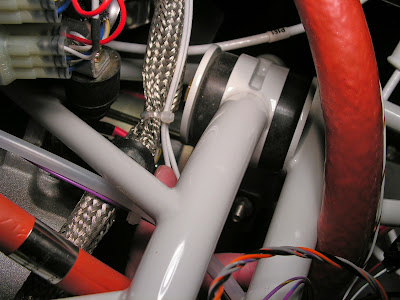
Step 10: To complete the routing leave the shielded ignition cable as it dives downward, turning aft instead to join the main wire bundle going through the cushioned clamp(not shown) attached to the WD-1221 Engine Mount Standoff. See Figure 2.
Step 11: Locate the WH-J762(WHT/BLU) Ignition B Wire and the WH-J763(BLU) Ignition A Wire which are part of the main wire bundle going through the cushioned clamp attached to the WD-1221 Engine Mount Standoff.
Step 12: Insert the male pins into the ES AMP 1-480319-0 Female Connector as depicted in Figure 2. The WH-J763(BLU) Wire must correspond to the WH-J153(BLU) Wire of the WH-RV12-IGNITION Wiring Harness. Give the two wires a gentle tug to check for proper installation.

Step 13: Snap the ES AMP 1-480318-0 Male Connector into the ES AMP 1-480319-0 Female Connector and loosely tie wrap these wires to the main wire bundle for support (another wire will be routed through the same tie-wraps later).

This completes page 46-12.
Reference: 45A-08
Step 12: Route the WH-k766 (PRP) forked wire up the Start Power wire then attach the remainder to the Pitot line.

This completes page 45A-08.
Reference: Page 46-13
Step 1: Find the WH-K766 (PRP) forked wire installed on Page 45A-08. It will be tie-wrapped to the pitot line just to the left of the ignition modules. Locate the Electronic Connectors labeled A2 and B2. Locate the two violet colored wires pointed out by the arrows in Figure 1. The connector position opposite the violet wires in the bottom half of the connector will have no pin and wire installed. Remove the seal plug from these locations. Snap the forward most pin on the end of the soft start wiring harness into the unused socket of connector B2. Snap the remaining pin into the unused socket of connector A2. Give each wire a gentle tug to check for proper installation.


Step 2: Snap together the A2 and B2 sets of 6X ignition electrical connectors and install them back onto the metal ignition module bracket.

This completes page 46-13.
Reference: Page 46-14
Step 1: Find the WH-E764 (WHT/YEL) Oil Pressure Wire and the WH-P765 (RED) Oil Pressure Power Wire and separate them from the wire bundle penetrating the firewall. Strip the ends of these two wires and crimp on the called out spade terminals. See Figure 1.
NOTE: Reverse spade connector polarity to eliminate the potential for accidental misconnection. Do not tighten down the coolant hose tie wraps until the EGT and CHT wires are installed. See this page and Section 48.

Step 2: Connect the WH-00096 Oil Pressure Sensor Harness to the 456180 Oil Pressure Sensor as shown in Figure 2. Route the harness aft under the right side of the engine as shown in Figure 2. Tie wrap it to the valve pushrod assembly, coolant hose, and Gascolator To Fuel Pump Hose as shown in Figure 3.


Step 3: Connect the spade terminals on the WH-00096 Oil Pressure Sensor Harness to the spade terminals on the WH-E764 (WHT/YEL) and WH-P765 (RED) wires as shown in Figure 2.
Step 4: Builder's note: This is not done yet waiting to power EFIS system until wiring is done.) Check that the Rotax 456180 Oil Pressure Sensor is selected in your EFIS systems setup. Refer to the instructions supplied with your EFIS system.
Step 5: Connect the two sets of spade terminals together as shown in Figure 1.

This completes this work session on the RV-12 airplane and working on the engine wiring I'll pick up here in the next installment.

