Most of today was spent fitting and filling the weave on the cooing shroud for the RV-12 airplane. I did make a pattern using some cardstock that made life easier. Next it was time to fit the engine mount. I couldn't get Van's Aircraft method to work so came up with a different approach as shown below.
Reference: Page 46-05
Step 1: Fit the FF-1207 Cooling Shroud down over the cylinders and mark any location that interferes. Remove and sand to fit. Repeat this process until the fit is correct. Gaps should not exceed 3/16 inch and will be filled later with high temperature RTV sealant. Coolant hoses will apply some downward pressure on the cooling shroud helping to keep it in place.


Step 2: Draw a line on the engine case along the entire front and back edges of the shroud. Remove the cooling shroud and set aside.

This seemed like a good time to drill the 3/4 inch hole in the Cooling Shroud for the cooling hose for the electrical rectifier. So...
Reference: page 40-12 Step 1: Cut a 3/4 dia hole in the FF-1207 Cooling Shroud in the approximate location shown in Figure 1 on page 40-12 of the RV-12 airplane plans..

Not wanting to leave well enough alone I filled the fiberglass weave on the Cooling shroud with epoxy and microlight to give a smooth surface to paint. While it set up I went on to Step 3 on page 46-05.

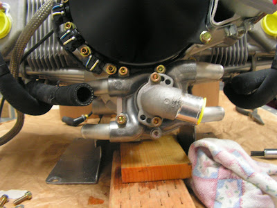
Step 3: Tilt up the back of the engine then support with a 2x4 wood block or equivalent under the oil outlet fitting on the bottom of the case.

Step 4: Squeeze open the clamps with a large pair of pliers or similar, and move the four spring type clamps forward along the lower coolant hoses to allow the hoses to be removed from the water pump. Beware of the possibility of residual coolant and have a catch pan and rags on hand. Pry/pull the hoses free.
This completes page 46-05.
Reference: page 46-06
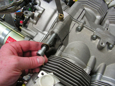
Step 1: Remove the crankcase allen screw located above and aft of cylinder three as it will be used as an engine mounting point.
Step 2: Apply masking tape to the inside surfaces of the WD-1220 Engine Mount Ring to prevent scraping the powder coat during installation. Remove the powder coating from the mating surface of the four engine mount bushings.


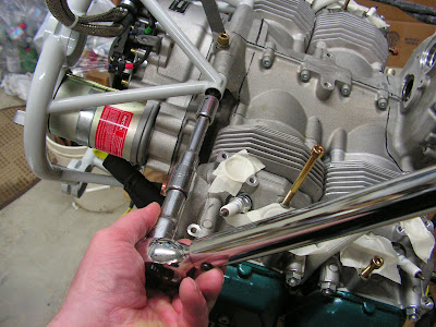
Builder's note: Try as I may, I couldn't get the process shown by Van's Aircraft in the plans for installing the engine mount to work. So, I came up with a alternative method shown step by step below.
Steps 3-5: Install engine mount.


Step 6: Bolt the WD-1220 Engine Mount Ring to the engine using the hardware called out in Figure 6 on page 46-06. Torque the mount screws to the value found in the ENGINE SUSPENSION FRAME ASSY. Section 28 of the Rotax Illustrated Parts Catalog. Remove the masking tape from the engine mount ring.
Step 7: Reinstall the four lower coolant hoses on the water pump and return the spring clamps to their proper locations.


This completes page 46-06 and this entry into the RV-12 airplane log.

