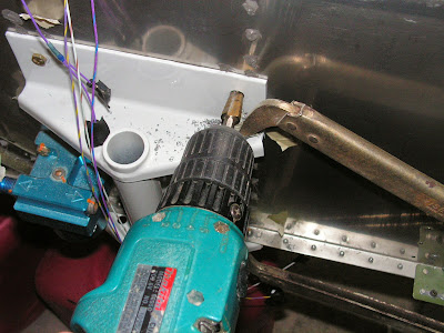
Today started where yesterday left off. As I stated before my nose gear top mounting holes did not align with those in the fuselage. In fact, they were off by a half a diameter. After talking to Van's Aircraft the best plan was to use clamps and lessen the preload on the gear so I could get the holes to align.
Reference: Page 46-10
Step 2: Bolt the right side of the WD-1201 Nose Gear Assembly to the F-1201C Firewall Bottom using an AN3 bolt to provide additional clamping pressure. Using the other 3/16 hole as a guide, final-drill 3/8 through the WD-1201 Nose Gear Assembly, F-1201C Firewall Bottom and WD-1204 Engine Mount Brackets. Deburr the hole.


Builder's note: Watch to make sure and wires in the tunnel are out of the way.
Step 3: Insert the called out AN6 bolt through the hole from inside the fuselage. From the front side of the F-1201C Firewall Bottom slip one EA 22002-15 Male Isolator and one WD-1221C-PC Washer over the bolt and tighten the nut to put clamping pressure on the left side of the WD-1201 Nose Gear Assembly. Remove the AN3 bolt from the right side and final-drill 3/8. Deburr. Insert one AN6 bolt into the right-side hole from inside the fuselage. Remove the nut, washer, and male isolator from the left side. Leave the bolts in place.

Builder's note: A chip chaser comes in real handy for removing any chips between the two parts. I also like using step drills as they drill very clean round holes.

Builder's note: I should add that when I did add mount the Rotax the engine bolt aligned perfectly.
Reference: 46-07
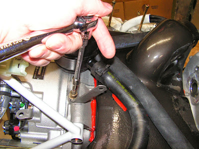
Step 3: Remove the masking tape from each coolant socket port. Verify the O-ring seals are still in place. Temporarily set in place the Hose / Expansion Tank Assembly on the engine but do not install the screws. Mark the FF-1207 Cooling Shroud on both sides of the outboard hose clamp of each coolant hose. Also mark where the cylinder two coolant hose contacts the cooling shroud inlet.
Step 4: Remove the upper Hose / Expansion Tank Assembly. Put an approx. 3/8" dia. blob of high temp. RTV between the marks made in the previous step so each blob will be located directly below each hose clamp. Also apply high temp. RTV between the marks that indicate where the coolant hose and cooling shroud inlet contact. Verify O-ring seals are still in place. Install the Hose / Expansion Tank Assembly on the engine. Torque the M6X20 allen screws to 90 in-lbs.


This completes page 46-07
Reference: Page 46-08
Step 2: Reposition the forward ignition module bracket using lines marked previously. Install the allen screw with Loctite 221 and torque it to 215 in-lbs.
Step 3: Remove masking tape from cylinder intake ports. Verify O-ring seals are still in place on each port. Install manifolds, ignition module and attached components and torque allen screws to 90 in-lbs.
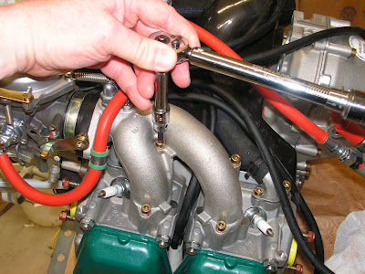
Step 4: Install small ignition harness clamp on top rear of ignition module but do not tighten it down yet. See Page 46-02, Figure 2. Do not connect A & B connector plugs at this time. Connect ignition leads to their corresponding spark plugs.

This completes page 46-08.
Reference: Page 46-09
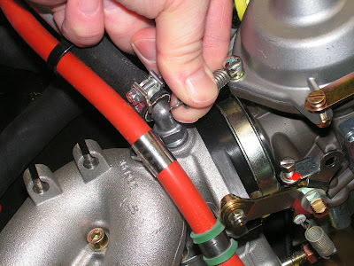
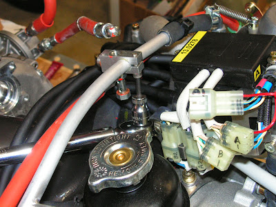
Step 1: Disconnect the damping spring (A) from the clamp bracket (B). Loosen the band clamp (C). Remove the carburetor with a slight turning and swivel action. Remove the band clamp (C). Disconnect the fuel line clamp (D) from the intake manifold by removing the retaining nut.

Step 2: Remove the two bolts securing the carburetor flange assembly to the intake manifold.

Step 3: Install the Drip Tray between the intake manifold and the carburetor flange assembly as shown in Figure 3. Verify that the O-ring is still in place on the flange of the manifold. Install the longer bolt to the outboard side. Use Loctite 221 and torque to 125 in-lbs.

Step 4: Install the band clamp onto the carburetor flange assembly. The clamp lugs and screw must be placed at the bottom or 6 o'clock position with the screw head facing outboard. Install the carburetor free of oil or grease. Tighten the band clamp against the spacer provided by Rotax which automatically sets the proper gap (.276 in. or 7mm) between the clamp lugs to prevent over tightening. Connect the damping spring. Install the fuel line clamp.


Repeat steps 1 through 4 for the right carburetor.
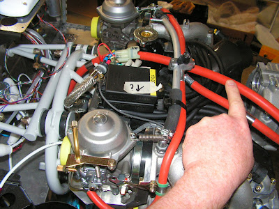
Builder's note: I ran into interference between the drip pan on the right carburetor and the ground wire from the ignition module. So I wrap the ground wire with Wire spiral guard. You can just see it in the second picture below. It's marked with a question mark to bring to the attention of my Technical counselor.

NOTE: When loosening or tightening the banjo bolts support the clamp block (fuel manifold) appropriately.
Step 5: Remove the two banjo bolts, copper rings and fuel hoses from the clamp block. Remove the Hose Nipple 3/4. It will not be replaced but keep it in a safe place. Be prepared to catch falling copper gasket rings.


Step 6: Loosen the allen screw and rotate the clamp block 180 degrees on the compensating tube. Doing so will place the main port on the forward side of the compensating tube. If the main port shifted to one side slide the clamp block back along the axis of the compensating tube to even out slack in the Clamp Block To Carb Fuel Hose Assembly.
Step 7: Tighten the allen screw M5X16 to 55 in-lbs.
Step 8: Remove the pilot jet from the banjo bolt M8X1X17 as shown in Figure 5. It will not be replaced but keep it in a safe place.

Step 9: Attach the Clamp Block To Carb Fuel Hose Assembly and the Pump To Clamp Block Fuel Hose. Torque the banjo bolt M8X1X27 to 90 in-lbs. Install the banjo bolt M8x1x17 finger tight for now to keep out debris.

This completes page 46-09. Next time I will install the Rotax on the RV-12 airplane!

