Sunday, March 30, 2014

Vans Aircraft RV-12 Airplane Build, Section 12: Empennage Fairings (part 6)

Reference for this entry: pages 12-08, 12-09; 3.0 hours

Today's work is again dealing with fitting the tailcone fairing on the RV-12 airplane.

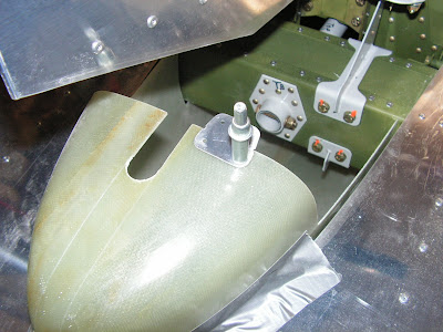
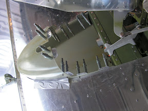
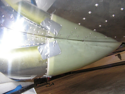
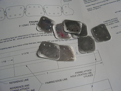
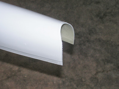
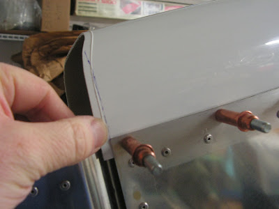
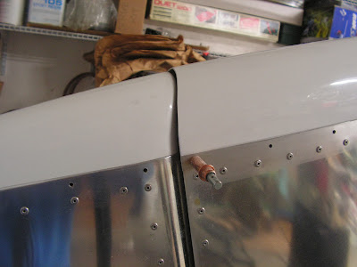
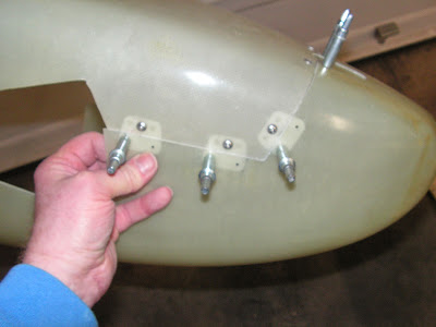
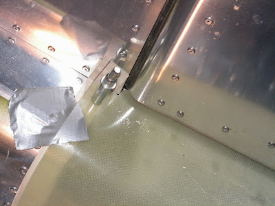
Step 1: Cleco the aluminum tabs to the lower fairing and install the AN526C632R8 screw in through the upper tailcone fairing into the tabs.


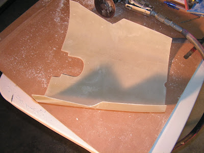
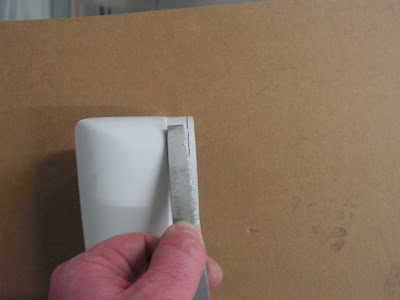
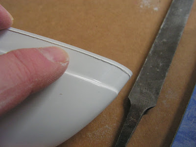
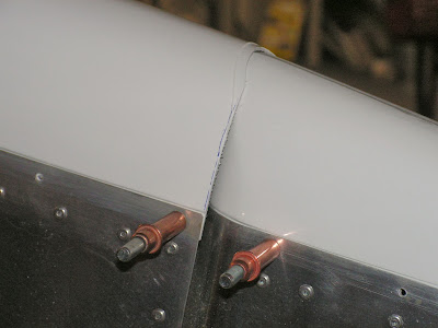
Step 2: Mark, separate and sand an even gap (1/32 to 1/16") between the mating surface on the upper and lower fairings.


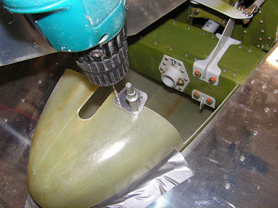
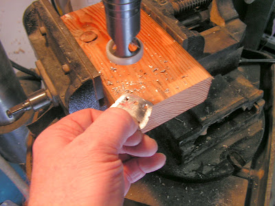
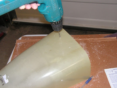
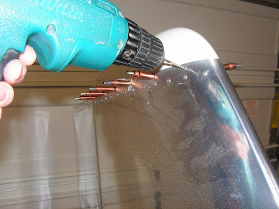
Step 3: Countersink #40 the rivet holes in the lower fairing


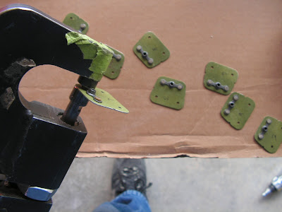
Step 4: Without over driving the rivets, rivet the tabs to the lower fairing using the rivets called out by Van's Aircraft.

Builder's note: I roughed the mating surface on the fiberglass and aluminum tabs. then epoxed the tabs in place setting the rivets while the epoxy was still wet.


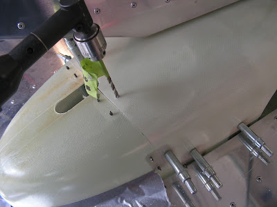
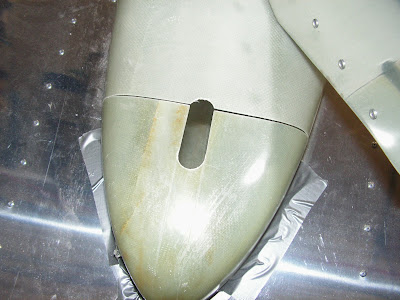
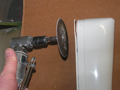
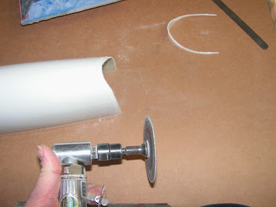
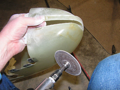
Step 5: trim the aft slot to the scribed lines in the lower fairing.


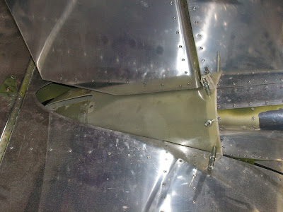
Step 6: Attach the two fairing piece together.


Step 7: NA as the rudder is already installed.

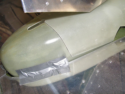
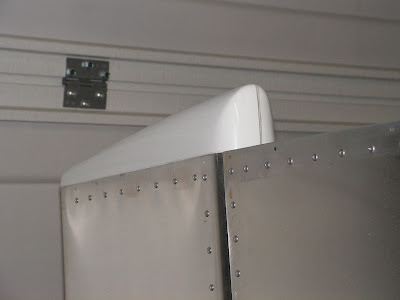
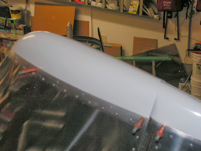
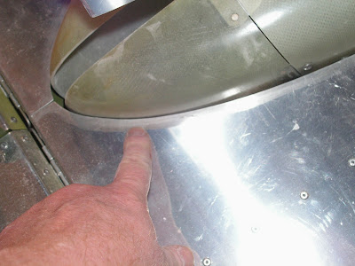
Step 8: Align the forward edge of the fairings with the fairing line on the masking tape. Adjusted the fairing as required to maitain a 1/8" gap between the upper fairing and the bottom of the rudder.


This completes page 12-08

Reference: 12-09

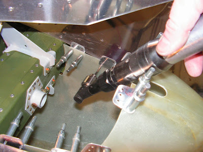
Step 1: Drill #40 the Upper tailcone Fairing at the inboard attach hole location and cleco the hole.


Step 2: Drill #40 the inboard hole in the left lower tape and then cleco.


Step 3: NA Install stabilizer.

Step 4: Adjust the fairing to provide at least a 1/8" clearance between the fairing and stabilizer skins.


Step 5: Repeat steps 1 & 2 for the right side of the tailcone fairing. Recheck clearances.


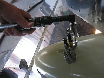
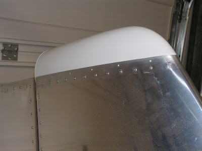
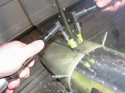
Step 6: With the fairings clecoed in place drill #40 the remaining fairing mounting holes into the tailcone.


Step 7: After deburring and removing any chips, Reattach the fairings and final drill #27 the mounting hole with the modified for fiberglass drill bit.


Step 8: Check the clearance between the stabilator assembly and the fairing through the entire travel of the stabilator. Mark and trim as needed to allow for at least a 1/8" clearance.


This completes page 12-09.

Saturday, March 29, 2014

Vans Aircraft RV-12 Airplane Build, Section 12: Empennage Fairings (part 5)

Reference for this entry: pages 12-07; 3.0 hours

The entry continues assembly of the tailcone fairing for the RV-12 airplane kitted by Van's Aircraft.

Step 1: With the upper fairing removed from the airplane. Align the aluminum tabs using the notches in the tabs as a reference.

Step 2: Match drill one of the holes in each tab #40 and celco. Then match drill the second hole in each tab.


Step 3: Reattach the upper fairing to the tailcone with the aluminum tabs clecoed to the outside of the lower tailcone fairing.


Step 4: Match drill #40 only the center hole on each of the aluminum tabs. Celco as you go. Then disassemble and clean out any chips and deburr.


Step 5: Cleco the Tabs to the inside surface of the lower fairing.


Step 6: Final drill #27 (with a bit modified for fiberglass) the center hole common with the upper fairing. Remove the upper fairing and claer away and chips.


Step 7: Machine counter sink the two rivet holes in each tab for the nutplate that goes towards the inside of the tabs..


Step 8: Rivet a nutplate to the inside surface of each aluminum tab.


This completes page 12-07 of the RV-12 airplane plans and this entry

Friday, March 28, 2014

Vans Aircraft RV-12 Airplane Build, Section 12: Empennage Fairings (part 4)

Reference for this entry: pages 12-06; 1.5 hours

Today's work centers around the continued installation of the tail fairing on the RV-12 airplane. As you will notice I left the empennage in place while doing this work. In hindsight this didn't make the task much easier and if my controls were not already rigged I don't think I would have done it myself.

Step 5: Align the front edge of the lower tail fairing for the RV-12 with the forward edge line marked on the tape installed in a earlier step. Then tape or clamp it in place.


Step 6: Align the front edge of the Upper tailcone Fairing with the mark on the tape, while aligning the 3/4" hole with the 3/4" slot in the lower fairing.


Step 7: Sand the edges called out in the RV-12 airplane plans for a good fit and minimal gap. These will be sanded to a final gap in a later step.


This is it for today.

Thursday, March 27, 2014

New Dynon Touch Screen Skyveiw Announced

Van's Aircraft and Dynon announced a new touch screen version of the Dynon Skyview will be available in April. If you currently have a Skyveiw it can be upgraded for $795 by sending it to Dynon (not Van's). There are also n\two new modules to agument the controls of the Skyveiw EFIS system.

In addition, they will be releasing a software update version 10.0. One of the new features I like about the update is a synthetic view of a standard six pack of flight instruments which should easy transition into the use of EFIS systems for those of us that are old school. Here is a link so to a short video, so check it out. Dynon Touch Screen

Sunday, March 9, 2014

Vans Aircraft RV-12 Airplane Build, Section 12: Empennage Fairings (part 3)

Reference for this entry: pages 12-06; 1.0 hours

Today starts the trimming of the tailcone fairing for the RV-12 airplane.

Step 1: Drill the two 3/4" holes with a unibit as called out by Van's Aircraft in the RV-12 airplane plans. Also drill the 4 #30 holes in the sides of the tailcone fairing.


Step 2: Trim the extra material from the lower tail cone fairing and sand to the scribed line. DO NOT remove the material between the two 3/4" holes at this time.


Step 3: Drill a 3/4" hole in the upper tail fairing. Also drill two #30 holes in the sides and top of the upper fairing as directed by Van's Aircraft.


Step 4: Trim the extra material from the top tailcone fairing and sand to the scribed line.


Builder's note: To fit the tail cone fairing onto the RV-12. I need to remove the Stabilator trim system as pictured. This completes todays work session on the RV-12 airplane kit.

Saturday, March 8, 2014

Vans Aircraft RV-12 Airplane Build, Section 12: Empennage Fairings (part 2)

Reference for this entry: pages 12-04, -05; 1.5 hours

Today I am still working on the tail fairing for the RV-12 airplane project. So let's get to it.

Reference Page 12-04

Step 1: Remove the rudder. Builder's note: I am leaving mine in place until painting. Because of this some steps are done in reverse. This is required so I could acess the front rivet on the Rudder Fairing.

Step 3: Rivet the Rudder tail fairing in place.


Builder's note: I used a hand rivet puller to reduce the likelihood of cracking the fairings.


Step 2: Rivet the V-Stab fairing into place.


Step 4: The rudder is already installed.

This completes page 12-04.

Reference: Page 12-05:

Step 1: Separate the F-1294C Tabs


Step 2: Mark masking tape per the dimensions provided by Van's Aircraft. Also make a mirror set.

Builder's note: I messed up the mirrored set and had to correct them before applying them.


Step 3: Place the AL tape on the upper left of the tail cone. Align the forward edge of the masking tape along the rivet heads as called out in the RV-12 airplane plans.


Step 4: Place the BL tape on the bottom left of the tail cone as called out by Van's Aircraft. Repeat these steps for the other side of the tailcone.


Step 5: Measure and mark the tailcone attachment hole locations as show in figure 3 of the RV-12 lans on page 12-05.


This completes page 12-05 and this entry into the RV-12 airplane builder's log.

Wednesday, March 5, 2014

Vans Aircraft RV-12 Airplane Build, Section 12: Empennage Fairings (part 1)

Reference for this entry: pages 12-02, -03; 2.0 hours

Today starts the attachment of the Empennage Fairings. The RV-12 plans call for the rudder and V-Stab to not be attached but I did the installation with them attached and it worked very well.

Step 1: Clean up the molded recess in both of the tip fairings. Leaving a nice square shoulder as directed by Van's Aircraft


Step 2: Trim away extra material off the bottom of the Rudder Trim cap.


Step 3: Trim away extra material on the V-Stab tip.


Step 4: Trim away the extra material at the rear of the V-Stab tip leaving 1/8" beyond the scribed line.


Step 5: Place the Rudder tip on the rudder. The edge of the recessed area of the tip fairing must be flush against the entire top of the rudder skins. Resolve any interference issues. Remove as little material as required to solve the problem.


Step 6: Hold and match drill #30 the fairing tip and rudder skins. Cleco each hole after it is drilled. Then remove the tip fairing, deburr and clean.


This completes page 12-02.

Reference: Page 12-03

Step 1: Fit the V-Stab fairing ensuring the recessed area seats correctly. Trim as needed.


Step 2: Match drill the V-Stab faring with a 330 drill bit. Cleco each hole as it is drilled.


Step 3: Ensure there is a smooth transition from the side of the fairing to the surface of the skins sand as needed.

Step 4: Trim the V-Stab fairing as shown on page 12-03 of the RV-12 airplane plans.


Step 5: Attach the rudder if it is not already attached.

Step 6: With both fairings attached mark and trim material from the V-Stab to allow for a 1/8" gap between the fairings with a max gap width of 1/4".


This complets page 12-03 and this entry. Until next time!