This weekend I attended the 16 hour E-LSA LSRI (Light Sport Repairman Inspection) course offered by Rainbow Aviation. This will allow me to get the certificate from the FAA to do the annual inspections on the RV-12 airplane or for that matter any ELSA I own in my life.
Is there a test? Yes, at the end of the course there is a 50 question multiply choice test. 80% is needed to pass the test. That being said, you will be well prepared during the course for the test.
Is there any retraining required to remain current? No.
Will this allow me to do inspections on a S-LSA? No.
Is the course built around RV-12? No. We spent time on all aspects of LSA including 2 stroke Rotax.
Will this give me all the inform needed to maintain a RV-12? No not really, but it is a great place to start. I would highly recommend the course.
Saturday, October 4, 2014
Wednesday, September 24, 2014
RV-12 Moving Day!
The garage is getting too small to complete the RV-12 airplane so today I'm going to move it down to a warehouse I have access to. I used a 17 foot U-haul truck to do the job.

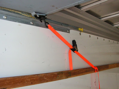
I tied the door up on both sides to insure it wouldn't crush the tail cone.
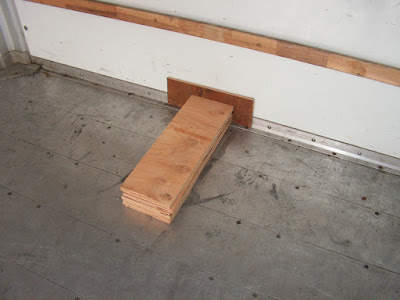
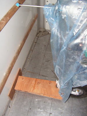
Nose blocks were used to block the wheel so as not to damage the pitot tube.
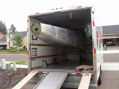
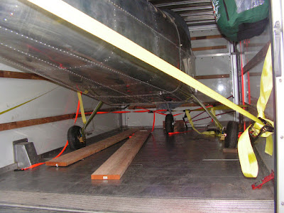
The move went very slick! The wings are already at the warehouse, these I moved in my Toyota truck.
I tied the door up on both sides to insure it wouldn't crush the tail cone.
Nose blocks were used to block the wheel so as not to damage the pitot tube.
The move went very slick! The wings are already at the warehouse, these I moved in my Toyota truck.
Sunday, August 3, 2014
Vans Aircraft RV-12 Airplane Build, Section 31A: Wing Electrical Interconnector Update (part 7) & Section 40: Lighting Kit
Reference: Pages 40-08, 40-09; 4.0 hours
Today will just about finish up the wing wiring for the RV-12 airplane lights.
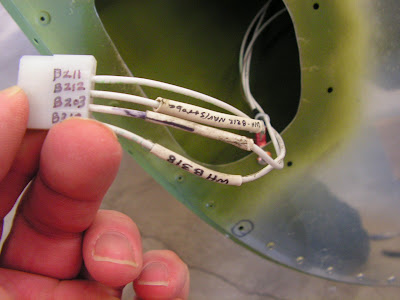
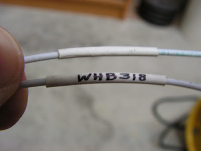
Step 8: Snap the female Molex pins on the ends of the WH-B211 (WHT) Nav/Strobe Ground Wire and WH-B212 (WHT) Nav Power Wire, WH-B203 (WHT) Strobe Power Wire, and the WH-B318 (WHT) Strobe Synch Wire into a male Molex connector housing in each wing tip.
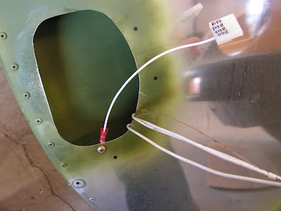
Step 9: Tie-Wrap all four wires together near the ring terminal on each wing tip to prevent the wires from rubbing on the edge of the access opening.
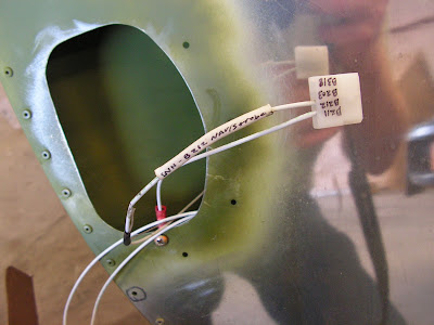
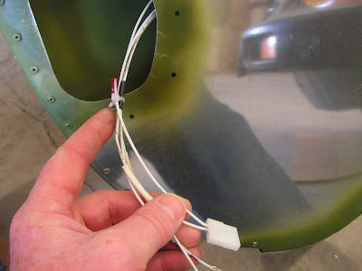
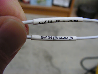
Step 13: Label the Molex connector housings as to which wire goes in what position.
That's it for today's work . Next I will start in on the prep for painting and finishing of RV-12 including the fiberglass parts. I have decided to paint the plane myself using Epibond epoxy primer and Aerothane for the top coat. Because this is a time consuming task with not much interest points for separate entries I will do one mass blog entry explaining the process and how long it took. So until then enjoy! I will also be doing an entry on how to register an ELSA aircraft between now and then as well.
Today will just about finish up the wing wiring for the RV-12 airplane lights.
Step 8: Snap the female Molex pins on the ends of the WH-B211 (WHT) Nav/Strobe Ground Wire and WH-B212 (WHT) Nav Power Wire, WH-B203 (WHT) Strobe Power Wire, and the WH-B318 (WHT) Strobe Synch Wire into a male Molex connector housing in each wing tip.
Step 9: Tie-Wrap all four wires together near the ring terminal on each wing tip to prevent the wires from rubbing on the edge of the access opening.
Step 13: Label the Molex connector housings as to which wire goes in what position.
That's it for today's work . Next I will start in on the prep for painting and finishing of RV-12 including the fiberglass parts. I have decided to paint the plane myself using Epibond epoxy primer and Aerothane for the top coat. Because this is a time consuming task with not much interest points for separate entries I will do one mass blog entry explaining the process and how long it took. So until then enjoy! I will also be doing an entry on how to register an ELSA aircraft between now and then as well.
Saturday, August 2, 2014
Vans Aircraft RV-12 Airplane Build, Section 31A: Wing Electrical Interconnector Update (part 6) & Section 40: Lighting Kit
Reference: Pages 40-09 (now page 40-10), 31A-06; 3.0 hours
Today I am going back to working on the wing tip lighting and wiring for the RV-12 airplane.
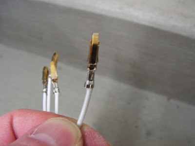
Step 8: Crimp male Molex pins on the ends of all the wires coming from the LN-200 Wing Tip Nav/Position/Strobe Light -Red & -Green.

Step 9: Snap the male Molex pin on the end of the black wire coming from the LN-200 Wing Tip Nav/Position/Strobe Light -Red & -Green into a female Molex connector housing opposite the position of the WH-B211 (WHT) Nav/Strobe Ground Wire.

Step 10: Snap the male Molex pin on the end of the red wire coming from the LN-200 Wing Tip Nav/Position/Strobe Light -Red & -Green into the female Molex connector housing opposite the position of the WH-B212 (WHT) Nav Power Wire.
Step 11: Snap the male Molex pin on the end of the yellow wire coming from the LN-200 Wing Tip Nav/Position/Strobe Light -Red & -Green into the female Molex connector housing opposite the position of the WH-B203 (WHT) Strobe Power Wire.

Step 12: Snap the male Molex pin on the end of the green wire coming from the LN-200 Wing Tip Nav/Position/Strobe Light -Red & -Green into the female Molex connector housing opposite the position of the WH-B318 (WHT) Strobe Synch Wire.

Step 13: Label the Molex connector housings as to which wire goes in what position.
Tomorrow I will pick up where I left off today.
Today I am going back to working on the wing tip lighting and wiring for the RV-12 airplane.
Step 8: Crimp male Molex pins on the ends of all the wires coming from the LN-200 Wing Tip Nav/Position/Strobe Light -Red & -Green.
Step 9: Snap the male Molex pin on the end of the black wire coming from the LN-200 Wing Tip Nav/Position/Strobe Light -Red & -Green into a female Molex connector housing opposite the position of the WH-B211 (WHT) Nav/Strobe Ground Wire.
Step 10: Snap the male Molex pin on the end of the red wire coming from the LN-200 Wing Tip Nav/Position/Strobe Light -Red & -Green into the female Molex connector housing opposite the position of the WH-B212 (WHT) Nav Power Wire.
Step 11: Snap the male Molex pin on the end of the yellow wire coming from the LN-200 Wing Tip Nav/Position/Strobe Light -Red & -Green into the female Molex connector housing opposite the position of the WH-B203 (WHT) Strobe Power Wire.
Step 12: Snap the male Molex pin on the end of the green wire coming from the LN-200 Wing Tip Nav/Position/Strobe Light -Red & -Green into the female Molex connector housing opposite the position of the WH-B318 (WHT) Strobe Synch Wire.
Step 13: Label the Molex connector housings as to which wire goes in what position.
Tomorrow I will pick up where I left off today.
Friday, August 1, 2014
Vans Aircraft RV-12 Airplane Build, Section 35: Landing Gear & Engine Mount (part 6)
Reference: Page 35-06; 3.0 hours
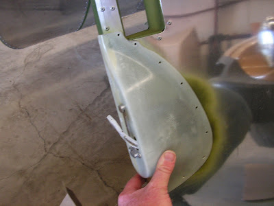
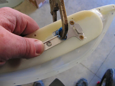
Today started the process of bleeding the brakes on the RV-12 airplane. What a pain!
Step 7: Fill the brake system with the brake fluid recommended in the wheel and brake package instructions. Follow the instructions in the wheel and brake package for bleeding the brake system (note that the loop around the base of the main gear legs is standard for RV aircraft and has not hindered the removal of air from the brake system).
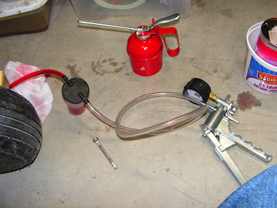
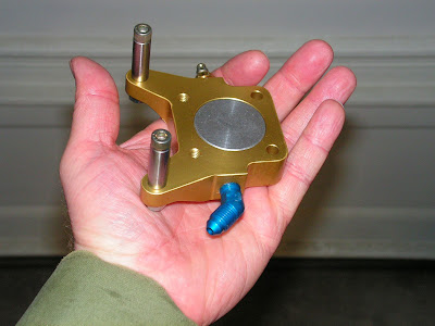
Builder's note: pictured above is the first bleeding system I used. I later built a pressure tank and used compress air to prime the system. It worked well on the left side but not the right side.
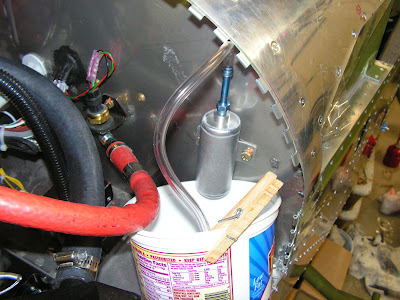
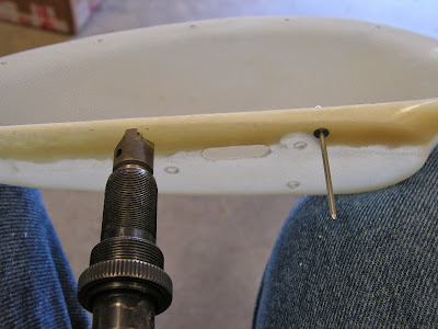
So, after talking with Matco (the brake manufacturer) I discovered if the piston is pressed all the way in (as pictured below) there is no room behind the piston to allow the fluid to flow into the system and press the piston out.
Builder's note: I did have some air bubbles that didn't want to flow out. So I loosened some of the strategically placed fitting and then forced the bubbles out as can be seen below.
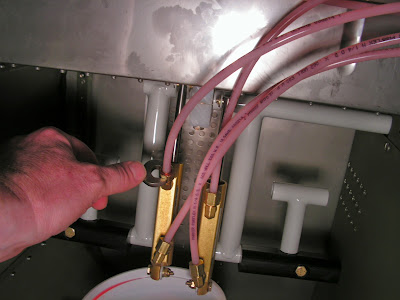
Checking the next day I did find a few leaks between the master cylinders and the brass elbows. Some of these I added an extra turn in tightening to stop them and one needed to be removed and resealed. This completed the priming and bleeding of the brake system.
Today started the process of bleeding the brakes on the RV-12 airplane. What a pain!
Step 7: Fill the brake system with the brake fluid recommended in the wheel and brake package instructions. Follow the instructions in the wheel and brake package for bleeding the brake system (note that the loop around the base of the main gear legs is standard for RV aircraft and has not hindered the removal of air from the brake system).
Builder's note: pictured above is the first bleeding system I used. I later built a pressure tank and used compress air to prime the system. It worked well on the left side but not the right side.
So, after talking with Matco (the brake manufacturer) I discovered if the piston is pressed all the way in (as pictured below) there is no room behind the piston to allow the fluid to flow into the system and press the piston out.
Builder's note: I did have some air bubbles that didn't want to flow out. So I loosened some of the strategically placed fitting and then forced the bubbles out as can be seen below.
Checking the next day I did find a few leaks between the master cylinders and the brass elbows. Some of these I added an extra turn in tightening to stop them and one needed to be removed and resealed. This completed the priming and bleeding of the brake system.
Tuesday, July 29, 2014
Vans Aircraft RV-12 Airplane Build, Section 42C: Skyview Update (part 9) & Service Bulletin 13-12-12
Reference for this entry: pages 42C-09, Service Bulletin 13-12-12; 6.0 hours
Today I will be working on the new ADAHRS stiffener for the Dynon Skyview. It goes in the tail cone of the RV-12 airplane just infront of the AHARS modual. Also this the day I choice to work on the SB 13-12-12 or sealing the avionics bay on the RV-12.

Reference: Page 42C-09:
Step 1: Counting from the aft most rivet remove the tenth rivet from the F-1283C J Stiffener. then cleco the stiffener to the J Stiffener wehere the rivet was just removed.

Step 2: Align the ADAHRS Stiffener perpendiculary to the J-Stiffener.

Step 3: Match-Drill #30 the holes in the Stiffener into the Top Skin . Deburr all of the holes.

Step 4: Blind rivet the ADAHRS Stiffener to the J_Stiffener and Top Skin from outside of the fuselage.
This completes Page 42C-09 and the installation of the ADAHRS Stiffener.
Reference: SB 13-12-12
Step 1. Remove, if/as required, the F-1240 Upper Forward Fuselage Skin and apply a release agent to the area of the F-1240 which mates to the F-1201H Upper Fwd Fuse Doubler.

Builder's note: I put aluminum tape (electrical would have been better) on the openings on the sides panels so I could seal these as well.
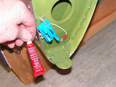
Step 2. Apply approx. 1/16 diameter bead of sealant (see above) to the entire length of the F-1201H Upper Fwd Fuse Doubler.
Builder's note: The service bulletin calls out using Black silicon or equilvalent. So I used fuel sealant with good results.
Step 3. Install (or re-install) the F-1240 Upper Forward Fuselage Skin and allow sealant to cure.

During this time I also sealed the steps to the fuselage.

That's it for today's work on the RV-12 airplane by Van's Aircraft.
Today I will be working on the new ADAHRS stiffener for the Dynon Skyview. It goes in the tail cone of the RV-12 airplane just infront of the AHARS modual. Also this the day I choice to work on the SB 13-12-12 or sealing the avionics bay on the RV-12.
Reference: Page 42C-09:
Step 1: Counting from the aft most rivet remove the tenth rivet from the F-1283C J Stiffener. then cleco the stiffener to the J Stiffener wehere the rivet was just removed.
Step 2: Align the ADAHRS Stiffener perpendiculary to the J-Stiffener.
Step 3: Match-Drill #30 the holes in the Stiffener into the Top Skin . Deburr all of the holes.
Step 4: Blind rivet the ADAHRS Stiffener to the J_Stiffener and Top Skin from outside of the fuselage.
This completes Page 42C-09 and the installation of the ADAHRS Stiffener.
Reference: SB 13-12-12
Step 1. Remove, if/as required, the F-1240 Upper Forward Fuselage Skin and apply a release agent to the area of the F-1240 which mates to the F-1201H Upper Fwd Fuse Doubler.
Builder's note: I put aluminum tape (electrical would have been better) on the openings on the sides panels so I could seal these as well.
Step 2. Apply approx. 1/16 diameter bead of sealant (see above) to the entire length of the F-1201H Upper Fwd Fuse Doubler.
Builder's note: The service bulletin calls out using Black silicon or equilvalent. So I used fuel sealant with good results.
Step 3. Install (or re-install) the F-1240 Upper Forward Fuselage Skin and allow sealant to cure.
During this time I also sealed the steps to the fuselage.
That's it for today's work on the RV-12 airplane by Van's Aircraft.
Sunday, July 27, 2014
Vans Aircraft RV-12 Airplane Build, Section 33: Miscellanea (part 1)
Reference for this entry: pages 33-02, 33-03, 33-04; 3.0 hours
Today I will start Section 33 for the RV-12 airplane. It's a section I jumped over earlier. But hay, there is no time like the present.
Step 1: Dimple the nutplate rivet holes in the Seat Floor Cover and the nutplates called out by Van's Aircraft. Rivet the nutplates to the floor covwer.
Step 2: Installing Flap Detent Bracket. On hold until later.
Step 3: Attach the end fitting of the lap belts to the Seat Attach Lugs using the called out hardware.

Step 4: Attach the end of the crotch straps to the Strap Lugs using the called out hardware.

Reference: 33-03
Step 1: Attach one end of the Shoulder Harness Cables to the Shoulder Strap Lug. No bushing are needed at this end.

Step 2: Attach the other end of the Shoulder Harness Cables to the Shoulder Harness. The bushing will allow the end fitting to rotate freely.

Step 3: Make the left and right Rudder Pedal Access Covers by removing the connecting metal between them.

Step 4: Dimple the nutplate rivet hole locations in the Rudder Pedal Access Covers and in the nutplates. Rivet them to the Access Covers.

Step 5: Install the Rudder Access Covers using the called out hardware.

Step 6: Cut the MS21266-1N Grommet to 2 13/32 inches and install on the Tunnel cover.

Step 7: Installing the tunnel cover will be done later.
Step 8: Dimple #19 the holes in the Baggage Cover as shown in the RV-12 airplane plans.
Reference: Page 33-04
Step 1: Test fit the Ant-abrasion Strip on the Mid Fuse Brace. With an ultra-fine felt tip marker and a striaght edge, make a line on the top of the brace as shown on page 33-04 of the RV-12 plans.

Step 2: Install the Anti-abrasive Strip, on the clean and dry mid-fuseBrace.
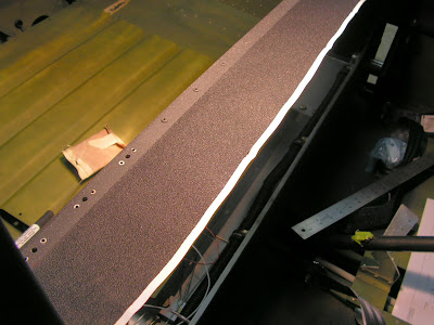
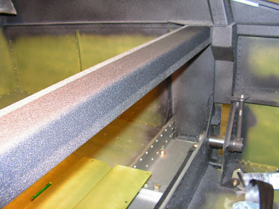
Builder's note: Nothing sticks well to the textured paint I used on the interior. So the bottom edge tends to pop loss when it is warm outside. So I will use Pliobond to stick it down. This section will be completed later in the finishing of the RV-12 airplane.
Today I will start Section 33 for the RV-12 airplane. It's a section I jumped over earlier. But hay, there is no time like the present.
Step 1: Dimple the nutplate rivet holes in the Seat Floor Cover and the nutplates called out by Van's Aircraft. Rivet the nutplates to the floor covwer.
Step 2: Installing Flap Detent Bracket. On hold until later.
Step 3: Attach the end fitting of the lap belts to the Seat Attach Lugs using the called out hardware.
Step 4: Attach the end of the crotch straps to the Strap Lugs using the called out hardware.
Reference: 33-03
Step 1: Attach one end of the Shoulder Harness Cables to the Shoulder Strap Lug. No bushing are needed at this end.
Step 2: Attach the other end of the Shoulder Harness Cables to the Shoulder Harness. The bushing will allow the end fitting to rotate freely.
Step 3: Make the left and right Rudder Pedal Access Covers by removing the connecting metal between them.
Step 4: Dimple the nutplate rivet hole locations in the Rudder Pedal Access Covers and in the nutplates. Rivet them to the Access Covers.
Step 5: Install the Rudder Access Covers using the called out hardware.
Step 6: Cut the MS21266-1N Grommet to 2 13/32 inches and install on the Tunnel cover.
Step 7: Installing the tunnel cover will be done later.
Step 8: Dimple #19 the holes in the Baggage Cover as shown in the RV-12 airplane plans.
Reference: Page 33-04
Step 1: Test fit the Ant-abrasion Strip on the Mid Fuse Brace. With an ultra-fine felt tip marker and a striaght edge, make a line on the top of the brace as shown on page 33-04 of the RV-12 plans.
Step 2: Install the Anti-abrasive Strip, on the clean and dry mid-fuseBrace.
Builder's note: Nothing sticks well to the textured paint I used on the interior. So the bottom edge tends to pop loss when it is warm outside. So I will use Pliobond to stick it down. This section will be completed later in the finishing of the RV-12 airplane.
Saturday, July 26, 2014
Vans Aircraft RV-12 Airplane Build, Section 31A: Wing Electrical Interconnector Update (part 5)
Reference: Pages 31A-04, 31A-05; 6.0 hours
Again I find myself working on the wing lighting wiring for the RV-12 airplane.
Reference: Page 31A-04
Step 8: On the left wing use the string previously installed to pull the Strobe Power Wire, Strobe synch Wire, and another string from the wing root into the wing tip. Repeat on the other wing.


Step 9: Attach all the crimped wires called out in Figure 1 on page 31A-05 to the Floating 8 Pos Connector Male. On the back side of the connector is a number for the wire position.
Step 10: Attach all the crimped wires called out in Figure 2 on page 31A-05 of the RV-12 airplane plans to the Floating 8 Pos. Connector Female.

This completes page 31A-04.
Reference: Page 31A-05>br/>
Step 1: On the left wing attach the ring terminal end of the Terminal Ground Wire to the Nose Rib and then repeat for the right wing.
Step 2: Install the Floating 8 Pos Connector Male and Female to the Standoffs.

This completes page 31A-05 and this work session on the RV-12 airplane.
Again I find myself working on the wing lighting wiring for the RV-12 airplane.
Reference: Page 31A-04
Step 8: On the left wing use the string previously installed to pull the Strobe Power Wire, Strobe synch Wire, and another string from the wing root into the wing tip. Repeat on the other wing.
Step 9: Attach all the crimped wires called out in Figure 1 on page 31A-05 to the Floating 8 Pos Connector Male. On the back side of the connector is a number for the wire position.
Step 10: Attach all the crimped wires called out in Figure 2 on page 31A-05 of the RV-12 airplane plans to the Floating 8 Pos. Connector Female.
This completes page 31A-04.
Reference: Page 31A-05>br/>
Step 1: On the left wing attach the ring terminal end of the Terminal Ground Wire to the Nose Rib and then repeat for the right wing.
Step 2: Install the Floating 8 Pos Connector Male and Female to the Standoffs.
This completes page 31A-05 and this work session on the RV-12 airplane.
Friday, July 25, 2014
Vans Aircraft RV-12 Airplane Build, Section 31A: Wing Electrical Interconnector Update (part 4) & Section 40 Lighting Kit
Reference: Pages 40-08, 31A-04; 2.0 hours
Today's work on the RV-12 airplane is a combination of installing the wing tip lights and the new wing connection system. I will say some of these wire runs would have been much easier to install back when the other wiring was going into the wing.
Reference: page 31A-04
Step 4: Fabricate two WH-B203 Strobe Power Wires 153 inches long from 18 gauge wire.
Bold Step 5: Fabricate two WH-B318 Strobe Synch Wires 153 inches long out of 18 gauge wire.
Step 6: Strip one end of all the fabricated wires then crimp on a interconnector pin.
Step 7: NA (tip lights have not been installed) Remove the Wing tip Nav Lights and pull the male Molex connector housing through the oval shaped hole in the wing Extensions.
Reference: Page 40-08
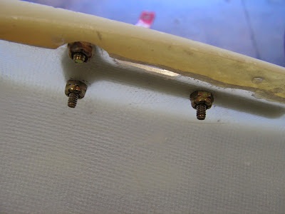
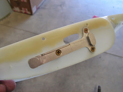
Step 1: Using the dimples molded in the face of the Extensions to align the Wing tip lIght mounting Brackets. Clamp the bracket in place then match dril#27 the holes in the mount brackets into the extensions.
Step 2: Done previously Remove the material from inside the oval area on the extensions to the scribed line.
Step 3: Machine countersink 120 degree all attach holes in the upper flange of the Extensions for the head of a CS4 rivet. Finish the edges of the part.
Step 4: Attach the Wing Tip Light bracket using the called out hardware.
Step 5: Make two WH-B211 Nav/Strobe Ground Wires 6 inches long from 18 gauge wire. Attach a ring terminal on one end and a female Molex pin on the other of each wire.
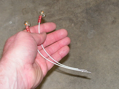
Step 7: Trim and strip the WH-212 Nav/Strobe Power Wire in each wing tip to match the length of the Ground wires. Crimp a female Molex pin onto the end of each nav/strobe power wire.
This completes today's work on the project. I have jumped over a few steps but these will be completed in the next few entries.
Today's work on the RV-12 airplane is a combination of installing the wing tip lights and the new wing connection system. I will say some of these wire runs would have been much easier to install back when the other wiring was going into the wing.
Reference: page 31A-04
Step 4: Fabricate two WH-B203 Strobe Power Wires 153 inches long from 18 gauge wire.
Bold Step 5: Fabricate two WH-B318 Strobe Synch Wires 153 inches long out of 18 gauge wire.
Step 6: Strip one end of all the fabricated wires then crimp on a interconnector pin.
Step 7: NA (tip lights have not been installed) Remove the Wing tip Nav Lights and pull the male Molex connector housing through the oval shaped hole in the wing Extensions.
Reference: Page 40-08
Step 1: Using the dimples molded in the face of the Extensions to align the Wing tip lIght mounting Brackets. Clamp the bracket in place then match dril#27 the holes in the mount brackets into the extensions.
Step 2: Done previously Remove the material from inside the oval area on the extensions to the scribed line.
Step 3: Machine countersink 120 degree all attach holes in the upper flange of the Extensions for the head of a CS4 rivet. Finish the edges of the part.
Step 4: Attach the Wing Tip Light bracket using the called out hardware.
Step 5: Make two WH-B211 Nav/Strobe Ground Wires 6 inches long from 18 gauge wire. Attach a ring terminal on one end and a female Molex pin on the other of each wire.
Step 7: Trim and strip the WH-212 Nav/Strobe Power Wire in each wing tip to match the length of the Ground wires. Crimp a female Molex pin onto the end of each nav/strobe power wire.
This completes today's work on the project. I have jumped over a few steps but these will be completed in the next few entries.
Subscribe to:
Posts (Atom)

