Showing posts with label RV-12 page 49-04. Show all posts

Tuesday, June 24, 2014

Vans Aircraft RV-12 Airplane Build, Section 49: Cooling System (part 5)

Reference for this entry: page 49-04, 49-06, 49-07, 49-10; 3.5 hours

Today's entry is more work on the RV-12 airplanes cooling system. I called Van's Aircraft today because I couldn't find the hoses (H460) by name in the packing slips. As it turns out, it is the same as H173 3/16" fuel line.

Reference: 49-04

Step 4: Use the FF-1206C Hinge Pin to attach the Cooler Box Door Assembly to the FF-1206A Cooler Box Hinge. Safety wire the hinge pin to the FF-1204B Upper Cooler Box Rib. Use the provided safety wire holes in the upper cooler box rib.


This completes page 49-04.

Reference: 49-06

Step 4: Cut a 24 inch long piece of EA HOSE H460 to make the FF-1220 Overflow Bottle Hose.


Step 9: Slip the FF-1220 Overflow Bottle Hose over the stem on the 922 327 Overflow Bottle.


Step 10: Attach the 922 327 Overflow Bottle to the F-1201A Firewall Upper using the F-1201V Coolant Bottle Strap and hardware called out.


This completes page: 49-06

Reference: Page 49-07

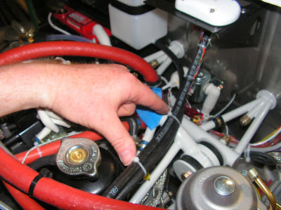
Step 1: Slide the free end of the F-1220 Overflow Bottle Hose over the barbed stem on the 922 665 Expansion Tank Assembly.


Step 2: Route the F-1220 Overflow Bottle Hose using tie-wraps.


Reference: Page 49-10

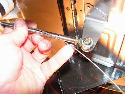
Step 5: Insert the bent end of the CT A-740 BLACK Push Pull Cable wire into the FF-1210 Cable End.


Step 6: Insert the cotter pin through the hole in the FF-1210 Cable End with the eyelet facing the side of the cable end (as shown in Figure 3 page 49-06). Rotate the cotter pin 90 degrees then bend the legs of the cotter pin around the cable end.

Step 7: Screw the jam nut onto the rod end as shown in Figure 3. Screw the rod end all the way into the FF-1210 Cable End until it bottoms out on the CT A-740 BLACK Push Pull Cable wire. Tighten the jam nut against the cable end.

Step 8: Using the hardware called out in Figure 3 attach the rod end to the FF-1205B Cooler Box Bracket.
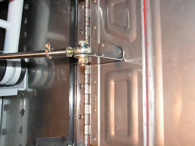


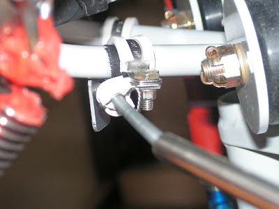
Step 9: Verify proper operation of the Cooler Box Door Assembly. If needed, loosen the clamps and reposition the CT A-740 BLACK Push Pull Cable so that the cooler box door assembly closes tightly leaving a 1/16 gap between the knob and the F-1201A-1 Instrument Panel. When satisfied safety wire the push pull cable to the cushioned clamp as shown in Figure 3 on page 49-06.


This completes page 49-10 and this entry.

Tuesday, June 10, 2014

Vans Aircraft RV-12 Airplane Build, Section 49: Cooling System (part 3)

Reference for this entry: page 49-04, 49-08, 49-09, 49-10; 6.0 hours

Today's contains with work on the RV-12 airplane's engine cooling system. I am adding a Builder's Gotcha only because it took three attempts to form a gasket on the Cooler Box Door. (some of us are slow learners;) I also a m jumping over the installation of the radiator until after the heater door control is completed. Because I can't see having to work around the hoses and radiator to install the control.

Step 1: Rivet the FF-1204A Cooler Box Face and FF-1206A Cooler Box Hinge to the F-1201C Firewall Bottom using the rivets called out by Van's Aircraft. Rivet the remaining holes common between the cooler box face and the firewall bottom.


Step 2: Rivet the FF-1204B Upper Cooler Box Rib and FF-1204C Lower Cooler Box Rib to the F-1201C Firewall Bottom using the call-outs in Figure 1.


Step 3: Rivet the FF-1204A Cooler Box Face to the FF-1204B Upper Cooler Box Rib and FF-1204C Lower Cooler Box Rib using the call-outs in Figure 1.


Step 4: Use the FF-1206C Hinge Pin to attach the Cooler Box Door Assembly to the FF-1206A Cooler Box Hinge. Safety wire the hinge pin to the FF-1204B Upper Cooler Box Rib. Use the provided safety wire holes in the upper cooler box rib.

Builder's note: This was not done until after the cooler door control was finished on 6/24/14.

Step 5: Cover the F-1201C Firewall Bottom with wax beneath the Cooler Box Door Assembly.

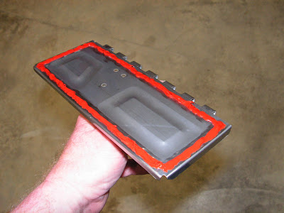
Builder's note: OK this is the GOTCHA. I tried packing tape, I tried PVA and then I final tried wax paper. The wax paper worked great! As it allowed me to look at the seal quality and RTV flow pattern before the RTV setup. I have included pictures of the failed attempt below for entertainment and education.

Step 6: Scour the aft face of the FF-1205 Cooler Box Door with Scotch Brite around the edge where the RTV gasket is depicted in Figure 2 on page 49-04.


Step 7: Add a bead of high temp RTV around the edge of the FF-1205 Cooler Box Door as shown in Figure 2 then close the Cooler Box Door Assembly firmly agains the firewall. Temporarily hold the door closed with tape from the end of the FF-1205B Cooler Box Bracket to the edge of the fuselage.


Builder's note: Here are some of the bad attempt below.


Reference: Page 49-08

Step 1: Modify a grommet to be used for firewall penetration. Using a socket and a vise, squeeze the grommet called out in Figure 1 in page 49-08, until the socket shears through the grommet (this will be accompanied by a distinct crunching sound).


Step 2: Install the firewall grommet from Step 1 into the control cable penetration location in the F-1201A Firewall Upper.


Step 3: Install the CT A-740 BLACK Push Pull Cable into the F-1202A Instrument Panel and through the firewall grommet installed in Step 2.

Builder's note: I had to chamfer the hole to get the control cable to set flush with the panel.


Step 4: Install a cushioned clamp on the F-1202B Panel Base to support the CT A-740 BLACK Push Pull Cable.


This completes page 49-08

Reference: 49-09

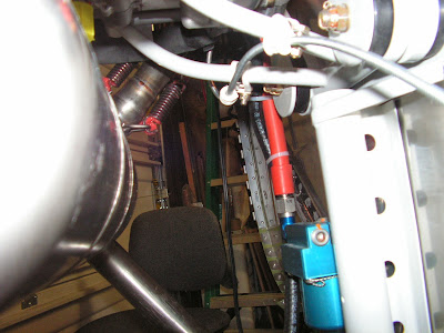
Step 1: Add three sets of cushioned clamps to the WD-1220 Engine Mount Ring routing the CT A-740 BLACK Push Pull Cable through each.


Step 2: Install the friction Comb between the lower set of cushion clamps.


Step 3: Pull the handle and attached wire of the CT A-740 BLACK Push Pull Cable completely out of the cable sheath.


Step 4: Using the dimensions in Figure 1 on page 49-09, trim the CT A-740 BLACK Push Pull Cable sheath.

This completes page 49-09.

Reference: Page 49-10

Step 1: Reinsert the CT A-740 BLACK Push Pull Cable into its sheath. Close the Cooler Box Door Assembly.

Step 2: Screw the jam nut all the way onto the rod end then screw the rod end all the way into the FF-1210 Cable End as shown in Figure 1. Using the bolt called out in Figure 1 temporarily attach the rod end to the FF-1205B Cooler Box Bracket.


Step 3: Push the CT A-740 BLACK Push Pull Cable wire in, leaving a 1/16 gap between the knob and the F-1202A Instrument Panel. Mark the location of the hole in the FF-1210 Cable End on the wire. Disassemble the rod end, nut and cable end from the FF-1205B Cooler Box Bracket.


This completes this work session on the RV-12 airplane.