Friday, February 28, 2014

Vans Aircraft RV-12 Airplane Build, Section 11: Empennage Attachment (part 4)

Reference: pages 11-07; 2.0 hours

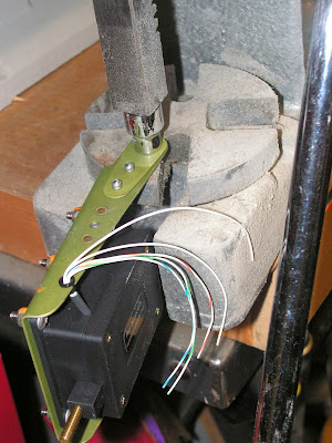
Today's entry is still deals with working on the electric trim system for the RV-12 airplane. There is a possible "Gotcha" I will address as the pieces are assembled.

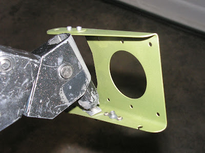
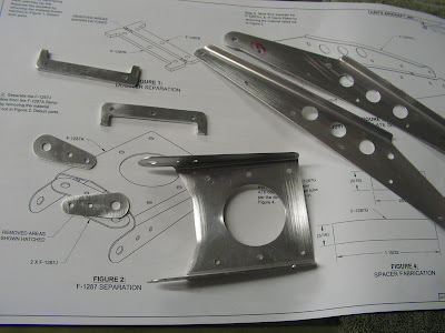
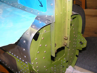
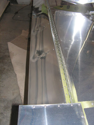
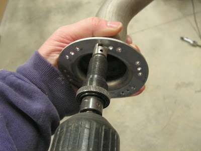
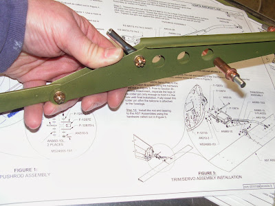
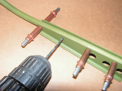
Step 1: Attach the clevis plates parts and hardware called out by Van's Aircraft on page 11-07. Cleco the plates to the Pushrod while paying attention to the orientation of the plates and rod.


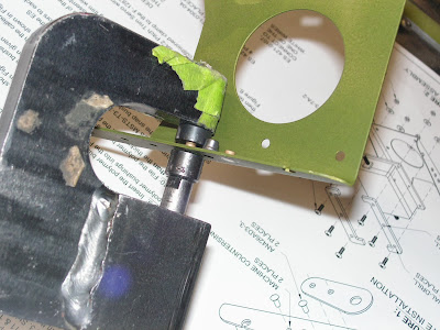
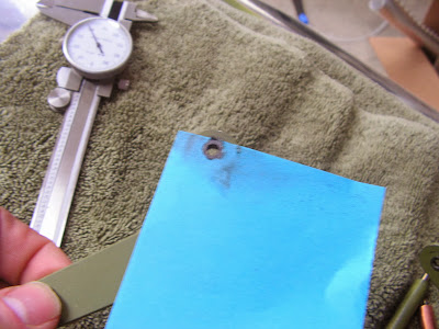
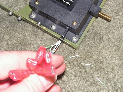
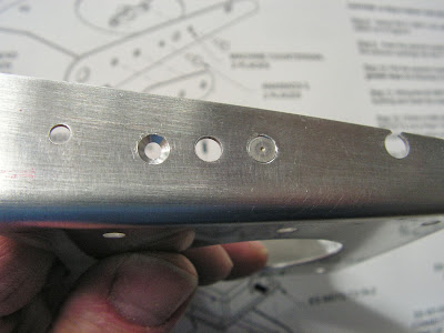
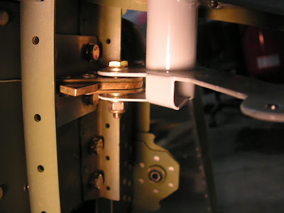
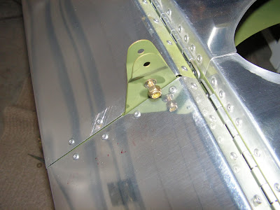
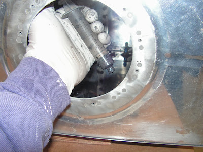
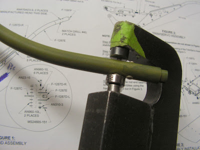
Builder's note: So here is a possible GOTCHA. When the clecos are inserted from both sides they can hit each other and will misalign the assembly as can be seen below. One possible fix is to trim the tall off the celco so they won't hit inside the tube. I didn't have a problem with this, but forewarned is forearmed.


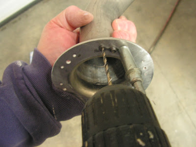
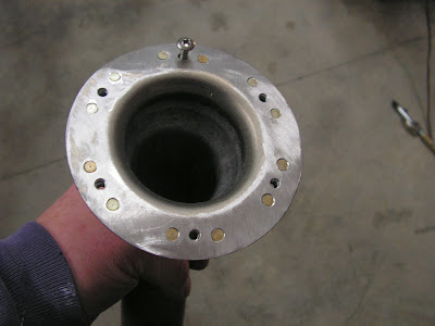
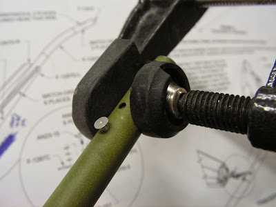
Step 2: With the assembly correctly aligned, match drill #30 into the push rod. Then remove the clecos (but not the hardware) and deburr and remove any chips.


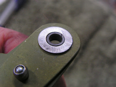
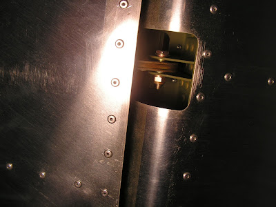
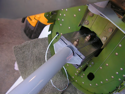
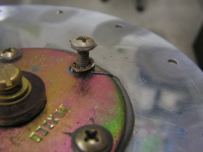
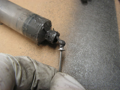
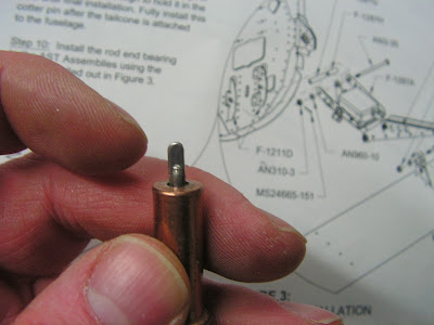
Step 3: Clamp the threaded insert into the end of the pushrod making sure the rivet holes are aligned. Note: Rivet is inserted just to align holes


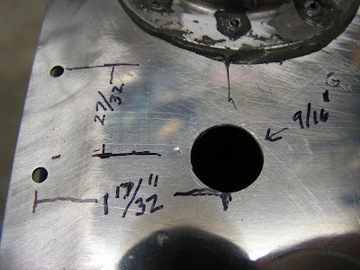
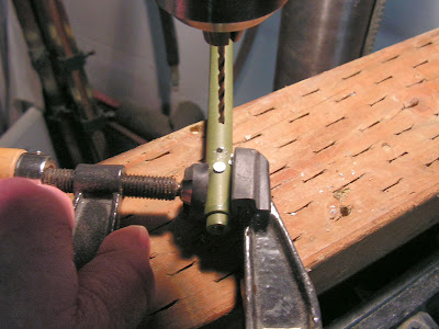
Step 4: Match drill #40 the threaded insert and pushrod.


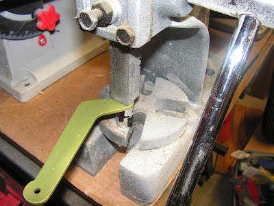
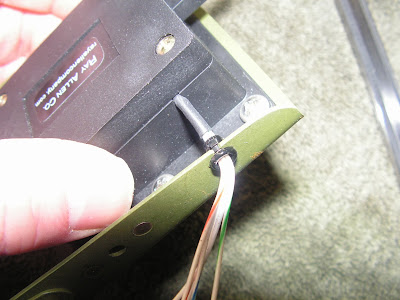
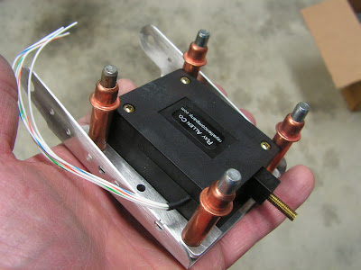
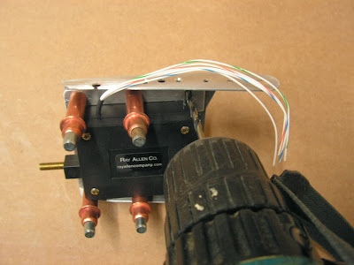
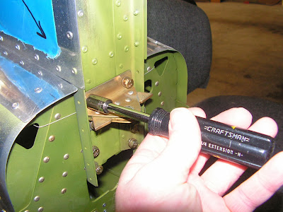
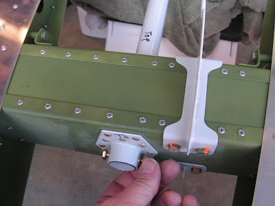
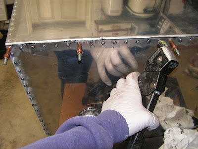
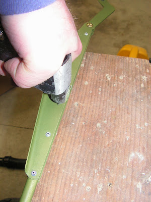
Step 5: Rivet the Clevis plates on while pressing towards the pushrod as each rivet is set. Rivet the threaded insert in.

Builder's note: I found using a hand riveter worked very well as the rivets across the tube from each other hit each other (just like the clecos did) until they are set. That's why you need to push down as the rivets are set.


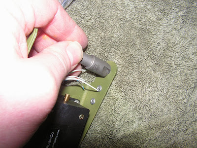
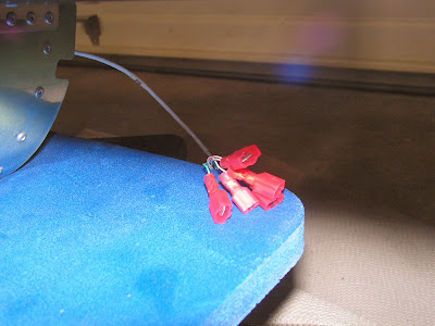
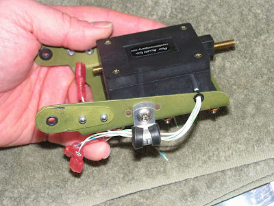
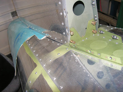
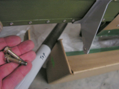
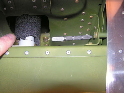
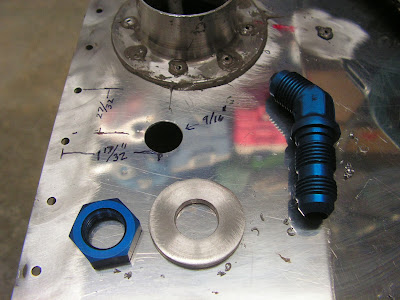
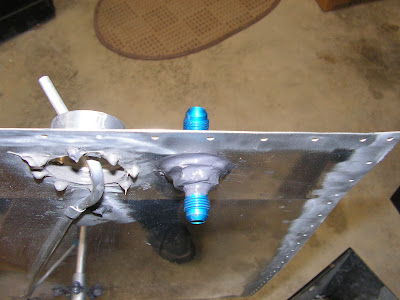
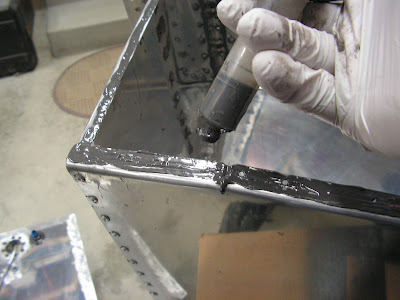
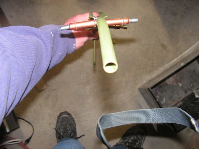
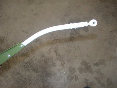
Step 6: Installed the rod end and jam nut to give the required length as outlined by Van's Aircraft. I then final painted the exposed pushrod.


This complete today's work on the RV-12 airplane . After the paint sets I will continue with the installation fo the servo trim system for the RV-12 airplane.

Monday, February 24, 2014

Vans Aircraft RV-12 Airplane Build, Section 11: Empennage Attachment (part 3)

Reference: pages 11-06; 2.0 hours

With the zinc chromate dry on the trim parts it's time to start assembly of the trim system for the RV-12 aircraft.

Steps 2 & 4: Rivet the nutplate to the servo tray (this is the older design new kits use molex plug). Also rivet the Doublers on the out side of the tray. NOTE: Direction of rivet head placement as specified by Van's Aircraft.


Step 6: Install the srevo on the trim tray.

Builder's note: Don't forget the doublers as I did during the first assembly! Also the RV-12 plans call out AN526-632R8 screws, but these were not supplied with my kit and are not listed on the hardware lists supplied by Van's Aircraft. However, the kit did come with AN526C-632R8 (stainless steel) so I used these instead. If I find this to be an error I will list it later as a Builder's Gotcha.


Step 7: Gives instructions on how to strip and double over the wire before installing the spade connectors.

Step 8: Deburred the servo link F-1287C (per RV-12 plans only deburr one side only of the bushing hole) and the Servo Tray previously.


Step 9: Insert the bushings into the link and servo tray.


Step 10: Filed the bushings to the dimensions given in this step by Van's Aircraft.

Builder's note: I used a thin washer as a file guide to keep the bushings square to almost the final thickness and then used thin aluminum sheet as a guide to finish these.


Step 11: Inserted the wire bushing and the servo wired into the tray.


Step 12: Installed one male terminal on one of the white wires coming out of the servo and female connectors to the remaining 6 wires.


Step 13: Crimped one female connector on one fo the white wires comming out of the tailcone trim wires and male connectors on the remaining 6 wires comming from the RV-12 tailcone.


Step 14: Inserted the servo wire leads through the cushion clamp and installed it temporarily.


This completes page 11-06 an this log entry. Please note many of the pictures above show no servo doublers installed on the servo, this is wrong and has been corrected later in my build!

Saturday, February 22, 2014

Vans Aircraft RV-12 Airplane Build, Section 11: Empennage Attachment (part 2)

Reference: pages 11-05, -06; 2.0 hours

Today continues the attachment fo the Empennage on the RV-12 airplane. I should note that there has been a update to this section by Van's Aircraft which replaces the spade connectors on the RV-12 airplanes trim system with a molex connector. After thinking long and hard about this I stayed with the original design. As the spade connectors have not given anyone problems and I like the use of the cushion clamp for strain relief of the wires.

Step 1-3 Separate the servo doublers, servo tray and the Clevis plates. Then deburr them.


Step 4: Fabricate the two spacers from the 5/16 inch aluminum tubing.


This completes page 11-05.

Reference: 11-06.

Step 1: Countersink for the nutplate attach rivet holes.


Step 4 & 5: Cleco the trim servo and Doublers to the servo tray and match drill the center holes, final drill the end holes.


This completes this entry. I still have to prime the parts I have been working on before assembly the stabilator trim system for the RV-12.

Friday, February 21, 2014

Vans Aircraft RV-12 Airplane Build, Section 11: Empennage Attachment (part 1)

Reference: pages 11-02, -03, -04; 2.0 hours

With the main gear installed on the RV-12 airplane kit, it's time to attach the empennage and finish the flight controls and linkages. So today starts the attachment of these. The plan is to leave them attach until needing to remove them for final painting.

Reference: page 11-02

Step 1: Remove the Lower hinge and hardware form the Vertical stabilizer Assembly.

Step 2 & 3: Place paper between the V-Stab and the top of the tailcone to prevent scratching the skins. Install the four lower bolt rear spar. Also installed the front hardware on the front spar as called out by Van's Aircraft in the RV-12 plans.


Builder's note: The bolt are not tightened until the next step.

Step 4: Install the Lower Hinge and tighten all the attachment bolts enough to prevent movement of the V-Stab assembly.


Step 5: Install the rudder onto the V-Stab.


Builder's note: I need a slightly different combination of washers so as not to sideload the hinges. These I noted on the plans for future reference.


Builder's Side Note: In the picture above, there should be rivets installed in the 10 rivet holes on the sides of the V-Stab Spar. These rivets were installed after this picture was taken.

Step 6: Check rudder for full moventand free travel.


This completes page 11-02.

Reference: page 11-03

Step 1: Remove the two AN4 bolts used to locate the "glued washers" on the stabilator hinge brackets. Also mark the "top" of the Counterbalance Arm. Remove the counter balance for the RV-12's Stabilator.


Step 2: Insert the counterbalance into the tailcone by rotating it 90 degrees. Then reinstall the counterbalance arm in it's original position with the hardware called out in the RV-12 plans by Van's Aircraft.


Builder's note: I temporarily put a piece of pipe insulation around the arm to protect it.


Step 3: Installed the Stabilator assembly using the tool shown above and the hardware called out.


Step 4: Check the travel of the Stabilator. Ensured the travel is only be limited by the hinge stops contacting the hinge brackets.


This completes page 11-03.

Reference: Page 11-04

Step 1: Form the two trim tab hinge pins by dulling the point of one end and making a 90 degree bind in the other according to the RV-12 airplane plans.


Step 2: Install both of the trim "AST" Assemblies to the Stabilator using the hinge pins from step 1.


Step 3: Connect the two AST Assemblies together using the hardware called out by Van's Aircraft.


Step 4 on this page deals with safety wiring the hinge pins on the AST tabs. However since I am remove these for painting before flight and final inspection these are being left until later and will be documented at that time. This completes today's work of the RV-12.

Monday, February 17, 2014

Vans Aircraft RV-12 Airplane Build, Section 37: Fuel Tank (part 8); new fuel tank gauge; new tank vent kit

Reference: pages 37B-03, 37-06, Service Bulletin 13-12-19; 2.25 hours

Step 19: Reinstall the Sender Plate with fuel tank sealant using the hardware called out and two new lock washers that are supplied by Van's Aircraft. Use a 1/16 inch thick layer of sealant between the plate and tank bulkhead. Tighten screws just enough to cause sealant to bulge evenly from underneath the perimeter of the plate.


Rechecked the continuity of the sender unit using a Ohm meter and everything worked within tolerances.

Reference: page 37-07

Step 5 - 8: Installed the nutplates that hold the fuel filler neck to the fuselage skin per Van's Aircrafts instructions.


So the RV-12 fuel tank is assembled and I'm going to let it sit a few weeks before pressure testing it. But there are plenty of other projects to work on in the meantime. The plan is to install the empennage onto the RV-12 airplane kit and then finish rigging the aircraft controls.

Sunday, February 16, 2014

Vans Aircraft RV-12 Airplane Build, Section 37: Fuel Tank (part 7); new fuel tank gauge; new tank vent kit

Reference: pages 37B-03, 37-06, Service Bulletin 13-12-19; 3.5 hours

Today and tomorrow will finish up most of the work for the RV-12's fuel tank. I am installing the new vent kit which is not required but seemed like a good idea since the fuel tank is disassembled for the Service Bulletin work. In looking over the plan revisions this vent is now part of the regular kit produced by Van's Aircraft.

Reference: 37B-03

Step 1: Removed Res Sender Plate previously.

Step 2: Using the template found on page 37B-03 (which was not to scale) measure and drill the hole in the fuel tank top. Deburr the hole.


Step 3: Finish installing the fuel fitting as out lined on page 37-05 step 5.

Step 4: Using the template supplied by Van's aircraft, drill the hole in the Baggage Bulkhead.


Reference page 37-06

Step 4: Install the new mechanical Fuel Gauge.

Sorry no pictures.

Step 5; Install the fluid fitting for the new RV-12 fuel tank vent.


Service Bulletin 13-12-19

Step 17: Reconnected the fuel return line to the fitting on the bottom of the fuel tank.

Reinstalled the fuel tank top after completing all internal work.


Turned tank upside down and put a dab of sealant on each new rivet.


I'm letting the fuel tank sit upside down overnight before completing the job of installing the sender unit plate.