Over the next two days the prescribed test flights and Van's flight cards were completed, with inspections between each flight.
A couple of things did surface during the test period and are as follows:
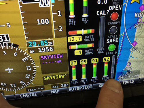
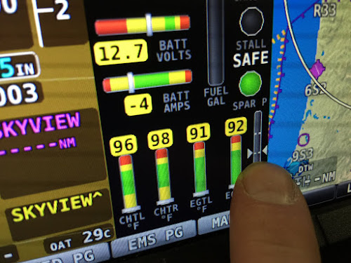
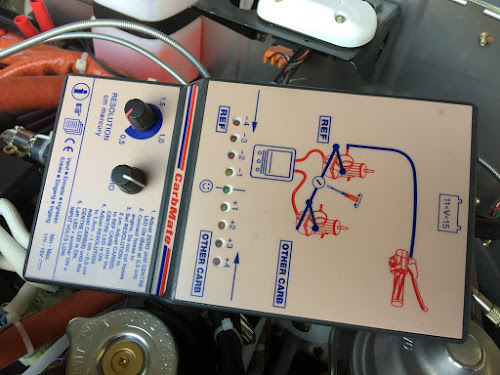
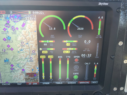
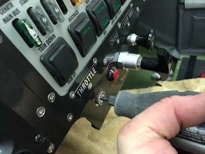
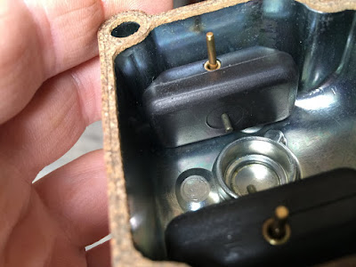
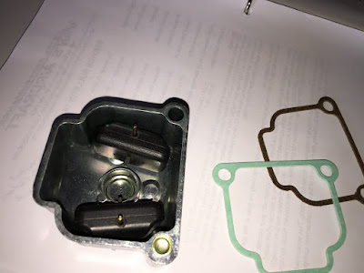
Idle was set ~100 rpm too high and was reset to 1450rpm.
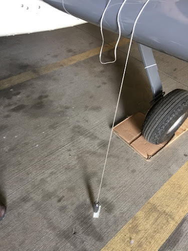
One of the landing gear bolts was found slightly low on the torque value when all the bolts were re-torqued.
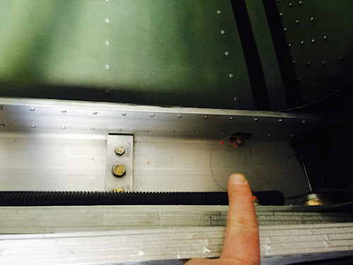
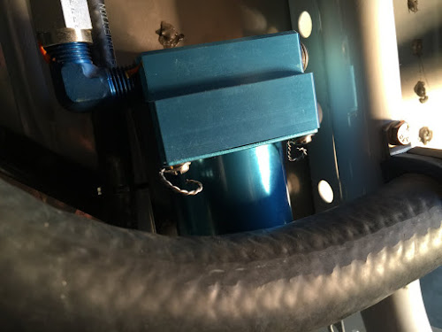
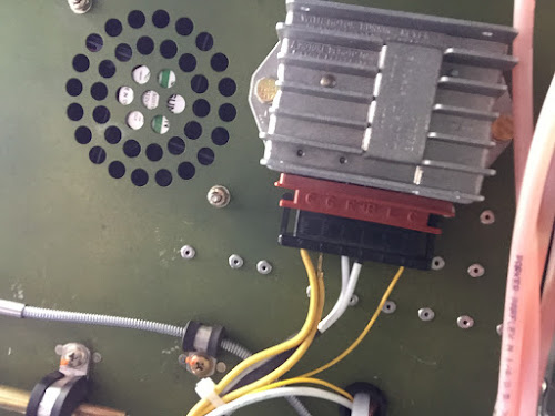
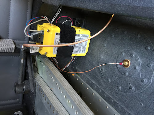
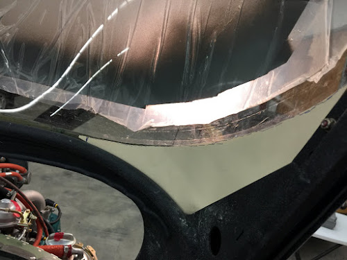
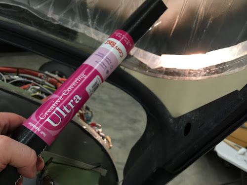
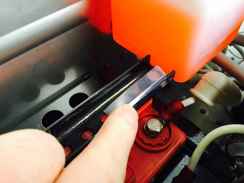
I placed a small piece of very thin UMHW tape over part of the battery frame as I was told this can short out when putting a trickle charger on the battery.
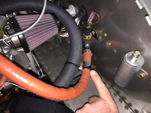
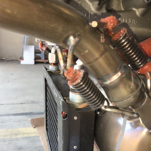
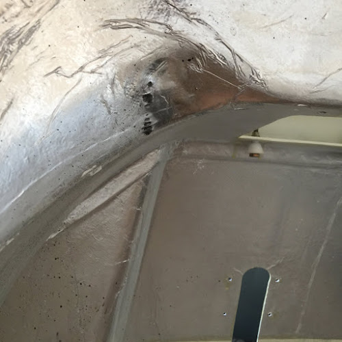
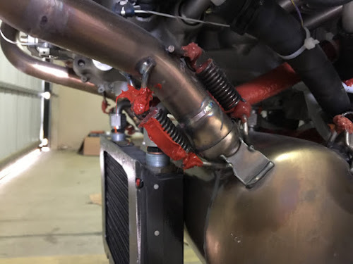
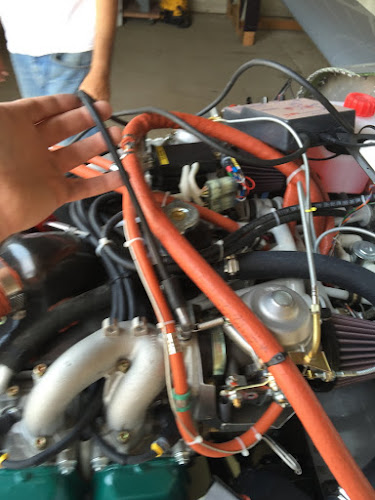
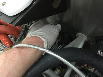
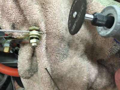
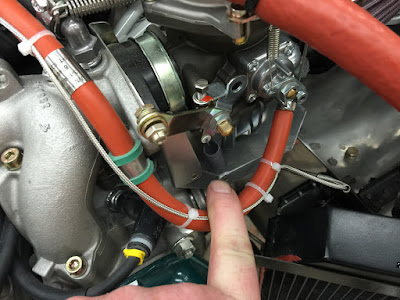
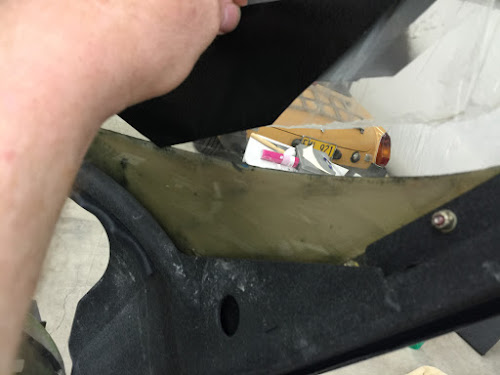
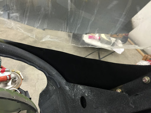
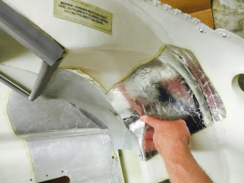
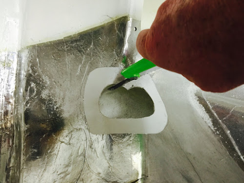
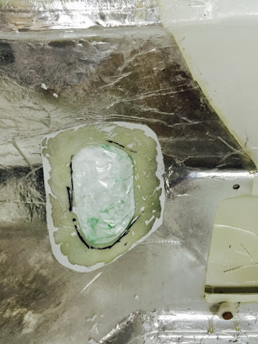
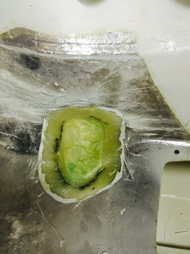
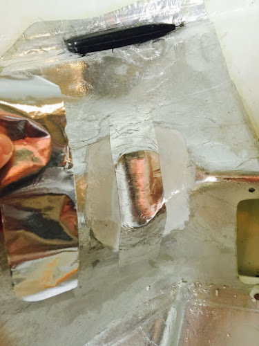
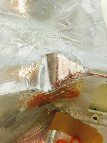
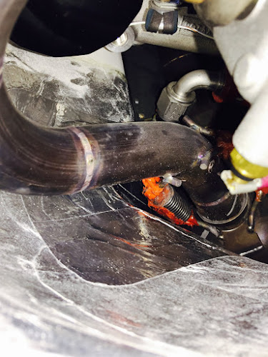
One of the exhaust springs was wearing on the cowl. So I cut a clearance hole and re-fiberglassed and refinished a depression in the inner cowl duct.
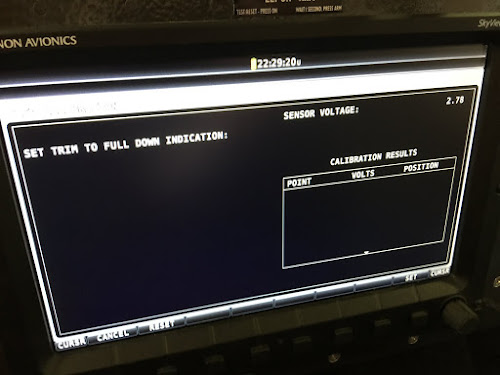
The Take-Off trim indicator was setup.
The left wing was heavy so the right wing was crimped per Van's RV-12 directions.
A rudder trim tab kit was installed and adjustment.
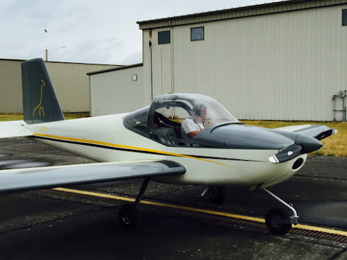
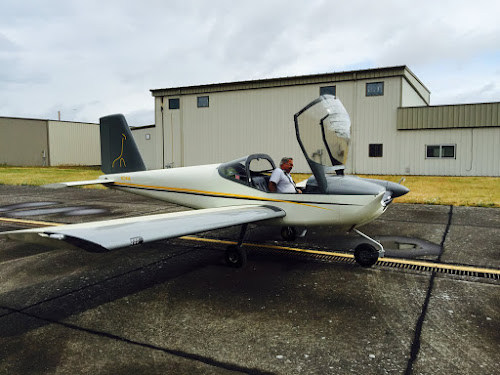
After all of this and the log book sign-offs, Mike and I spent and hour or so flying and preforming take-off and landings.
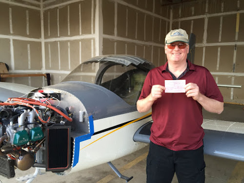
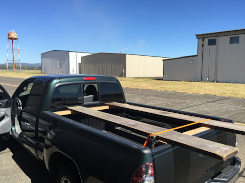
The next project was to take it up to Pacific Coast Avionics and get a transponder check.
The RV-12 is a great flying airplane! If you are thinking of building one get a test flight from Van's. It's a free test flight that will only cost $70,000:) Enjoy- Vern Smith