Sunday, September 29, 2013

Vans Aircraft RV-12 Airplane Build, Sections 25: Tailcone Attachment (part 5)

Reference: pages 25-05; 5.0 hours

Step 5: Final-Drill #36 and tap 6-32 all of the match-drilled holes in the Roll Bar Frames.


It nice to see the updated plans now have the Aft window sealed against rain and fuel.But I plan never to get fuel on the window as it will craze or fog.

Saturday, September 28, 2013

Vans Aircraft RV-12 Airplane Build, Sections 25: Tailcone Attachment (part 4)

Reference: pages 25-05; 2.0 hours

With my new pneumatic rivet puller in hand I am ready to finish riveting the tailcone on the RV-12 aircraft.

Step 1: Cleco the Fwd Turtle Deck Skins to the Fuselage and Tailcone Assembly.

Builder's note: I cleaned the primer off of the skin where the fuel tank filler neck will go as this will need to be sealed with fuel tank sealant.


Builder's note: I had some unwanted puckering of the tailcone skins that I am pointing at in the picture above (but you can't really see them." To fix this I pulled the turtle skins back and repent the tabs to remove them.


Step 2: Cleco the Aft Window underneath of the FWD Turtle Deck Skins.


Step 3: Match-Drill #40, beginning at either top inboard holes, the 3/32" holes from the Aft Window into the Roll Bar Frames. Cleco each hole before drilling the next.


Step 4: Rivet the Fwd Turtle Deck Skins to the Fuselage and Tailcone. Remove the Aft Window. Open all holes in the aft window using a #27 plexi drill bit.


Builder's note: When working with plexi I like to have the room temperature above 70 degree F. At this temperature the plastic is more flexible. Here is a good video on drilling plexi by the EAA and John Monnett:


I also drilled the aluminum skins to #27 at this time as well. Also it didn't mention it in the plans but smoothing the edges of the window is very inportant


NOTE: Optionally, now is a good time to paint the interior.

Builder's Note: I noticed a number of "holes" at the end of the tab slots that were not covered by the Turtle Deck Skins. I plan to seal these maybe with fuel tank sealant since it is paintable.


Tuesday, September 17, 2013

Vans Aircraft RV-12 Airplane Build, Sections 25: Tailcone Attachment (part 3)

Reference: pages 25-04; 4.5 hours

There has been a new revision (REV 1) to the RV-12 plans for this section which shows the wing fuselage doublers on the sides. I have already added these doublers per the service bulletin.

Step 1: Rivet the F-1284-L & -R Shear Clips to the F-1207C-L & -R Baggage Bulkheads as shown in Figure 1.


Step 2: Cleco the F-1273-L & -R Baggage Corner Skin in place. Underlap the F-1270-L & -R Left and Right Side Skins, F-1270A & F-1270B Side Skin Doublers and F-1276 Bottom Skins. Overlap the Tailcone Assembly skins as shown in Figure 1 and 2.

NOTE: The clecos in the F-1273-L & -R Baggage Corner Skins that are called out in Figure 2 mark holes that will be left open in this section.


Step 3: Rivet the Tailcone Assembly skins, the holes common to the Tailcone and Fuselage Assembly and the F-1273-L & -R Baggage Corner Skins using rivets called out in Figure 2. Rivets on the right side are a mirror of the left.Omit the holes covered by tape. Rivet the holes common to the F-1270-L & -R Skins, F-1280A & F-1270B Side Skin Doublers and F-1273-L & -R Baggage Corner Skins as shown in Figure 2. Remove the tape that was applied earlier in this section.


Today's work period ended abruptly when my Rivet puller died:( It has done a great job through both the RV-10 and RV-12. I tried replacing the seals again but the cylinder was scored and it just leaked fluid all over the place. Oh well until next time.

Monday, September 16, 2013

Vans Aircraft RV-12 Airplane Build, Sections 25: Tailcone Attachment (part 2)

Reference: pages 25-03; 1.5 hours

Well the fuselage of the RV-12 airplane is about to get much longer!

CAUTION: To avoid water penetration, upper skins need to overlap outboard of lower skins and forward skins need to overlap outboard of aft skins.

Step 1: Support the Fuselage and Tailcome Assemblies on saw horses. Bring the Tailcone Assembly to the aft of the Fuselage Assembly. Place the forward edge of the F-1282-L & -R Bottom Skins on the aft edge of the F-1276 Bottom Skin as shown in Figure 1 on page 25-02. Insert the forward edge of the tailcone bottom skins between the F-1207B Baggage Bulkhead and the fuse bottom skin as shown in Figure 4. Cleco the tailcone bottom skins to the fuse bottom skins. Lift the aft end of the tailcone and guide the tailcone skins outboard of the F-1255-L & -R Longerons and inboard of the F-1270-L & -R Fuselage Side Skins. The F-1279-L & -R Upper Skins are outboard of the fuselage side skins, see Page 25-04, Figure 2. Cleco the lower half of the Tailcone Assembly to the Fuselage Assembly in about ten places. Shake the aft end of the Tailcone Assembly up, down, left and right to ensure that the clecoes are set completely.


Step 2: Cleco the F-1207E-L & -R Shoulder Strap Lugs to the inboard surface of the Tailcone Assembly skins as shown in Figure 2.


Step 3: Rivet the F-1207E-L & -R Shoulder Strap Lugs to the Tailcone Assembly skins using rivets called out in Figure 2. Capture the upper flange of the F-1207D-L & -R Baggage Bulkhead Channels when riveting the two forward holes of the shoulder strap lugs.


Step 4: Place masking tape over all of the forward holes in the upper tailcone skins as called out in Figure 3. Taped holes will be riveted later in this section.

That's all the time I had today. Until tomorrow.

Sunday, September 15, 2013

Vans Aircraft RV-12 Airplane Build, Sections 42D: SkyView Update (part 2)

Reference: pages 42D-14, 42D-15, 42D-16, 42D-18, 42D-21, 42C-19; 5.5 hours

Before continuing with the installation of the tailcone on the RV-12 airplane, there are a few avionic wiring jobs that will be much easier to finish at this time.

NOTE: Snap bushing inserted on this page are to be used for wires routed through the F-1202F and F-1203A Bulkheads in the remainder of this section.

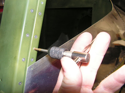
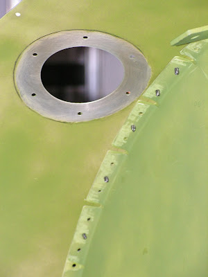
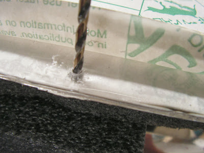
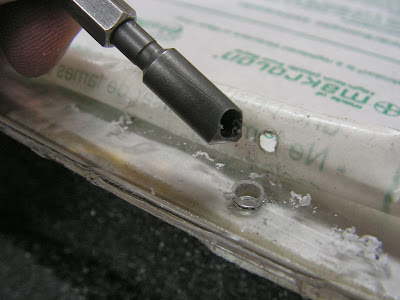
Step 1: Drill #30 a pilot hole in F-1203A Bulkhead using the dimensions given in figure 1 on page 42D-14 of the RV-12 airplane plans. Use a step drill to enlarge the #30 hole to 3/4. Insert a snap bushing into the hole per the callout in figure 2.

Step 2: Drill #30 a pilot hole in F-1202F Bulkhead using the dimensions given in figure 3. Use a step drill to enlarge the #30 hole to 3/4. Insert a snap bushing onto the hole per the callout in figure 2.

Builder's note: The two above steps were completed earlier but I reconfirmed that the steps have been completed.

This completes page 42D-14.

Reference page 42D-15

Page 42D-15 talks about the various ways that the update could be wire and provides some good information. The big thing for my build is that I am using the the following harness:
WH-RV12_TUNNEL + WH-00036 = WH-00046
WH-RV12-OPTIONAL + WH-00025 = WH00045 & WH-00025


The WH-00026 Option Conversion Harness combines both the WH-00045 Options Harness and WH-00025 SkyView AutoPilot Harnesses into one harness that make the same two connections to the AV-50000A RV-12 Control Module. When asked in Section 42C to install either the options or autopilot harnesses simply install the appropriately labeled harness on the WH-00025 instead.

Reference 42D-16

Step 1: Remove the backshell from the main 25-pin d-sub on the WH-RV12-OPTIONAL harness. Check that WH-F193(WHT/BLK) and WH-F192(ORN) are installed as shown in figure 1 on page 42D-16. If the wires are not installed but loose in the harness install ES SA-1017 Female D-Sub Sockets on the end of each wire per the instructions in Section 5W Electrical Wiring Notes, Repairing D-Sub Pins then insert them into the correct locations as shown in figure 1 on page 42D-16 of the RV-12 airplane plans.


Step 2: Find the wires going to the AP-74 25-pin d-sub from the main 25-pin d-sub on the WH-RV12-OPTIONAL harness. The AP-74 25-pin d-sub will be no longer used with the SkyView sytem. Coil and tie-wrap this d-sub in a safe location. As an option cut off this d-sub and heat over the end of each wire.


Step 3: Install the backshell assembly back onto the main 25-pin d-sub on the WH-RV12-OPTIONAL harness.


Builder's note: I didn't shrink the heat shrink tubing as my guess is I will need to install additional wires later in the build.

This completes page 42D-16. Page 42D-17 will be completed later.

Reference: 42D-18

Step 1: Pull excess wire from the WH-RV12-TUNNEL and WH-RV12-OPTIONAL harnesses down through the Panel Base until the backshells of these harness are in the approximate location shown in figure 1 on page 42D-18. Route the WH-RV12-TUNNEL and WH-RV12-OPTIONAL wiring harnesses through the slots for snap bushings in the left Com Support.


Step 2: Slit a snap bushing saved from the Inst Stack Supports previously in this section then install it around all wires and the Aft Pitot Tube going through the Com Support except the WH-RV12-OPTIONAL harness. Insert the bushing into the lower snap bushing slot in the com support.

The remaining steps on this page will be completed after the pitot tube and other wiring is ran.

Reference: 42D-21

Step 3: Route the WH-P323 (WHT) four conductor shielded wire, twisted HW-319 (GRN) and WH-F320(BLU) wires and twisted WH-F321 (WHT/GRN) and WH-322(WHT/BLU) wires along the path of the WH-RV12-TUNNEL wrining harness to the tailcone area location of the magnetometer.


Step 4: Tie-wrap routed wires as required.

NOTE: Reference page 31-12 for the remaining steps on this page.

Step 5: Find the ES 9 pin BACKSHELL 2 on the end of the WH-RV12-TUNNEL wiring harness disconnected.

Builder's Note: The above step doesn't really apply because this wire harness was never connected to the magnetometer.

Extract the remaining wires from the ES-205203-3 9-pin D-Dub. These wires will no longer be used or connected at the AV-50000A RV-12 Control Module. Fold the wires back and tie-wrap them to the wire run along the F-1208 Bulkhead.

Builder's note: Since these wires are not used I estracted them from the wire harness and removed them from the airplane. I don't like extra wires just running around.

Step 6: Find the WH-P323(WHT) four conductor shielded wire, twisted WH-F310(GRN) and WH-F320(BLU) wires and twisted WH_F321(WHT/GRN) and WH-322(WHT/BLU) wires routed previously to the tailcone area coming from the WH-00036 RV-12 Tunnel Conversion Harness and insert them into the ES-205203-3 9-pin D-Sub as shown in figure 1 on page 42D-21 of the RV-12 aircraft plans. Install the ES 9 PIN BACKSHELL 2 onto the 9-Pin D-Sub.


Step 7: 
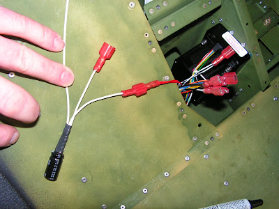
Separate out the WH-RV12-OAT wiring harness RED, YEL, and BLU. These come from a multi-conductor shielded wire. Remove 3 inches of the shield then clip the RED wire 1 inch from the end of the shield. Cover the exposed shield (and RED wire) with a piece of heat shrink. Strip the ends of the BLU and YEL wires. Attach the BLU and YEL wires to the WH-00008 SkyView OAT Connector Harness using the butt splices called out in figure 2 on page 42D-21.


Reference: page 42C-19:

Steps 3 & 4: Install the OAT wiring harness and the Fuselage Harness to the aft side of the ADAHRS 200.

This completes page 42C-19.

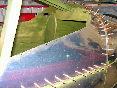
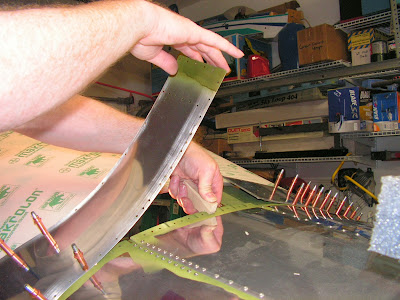
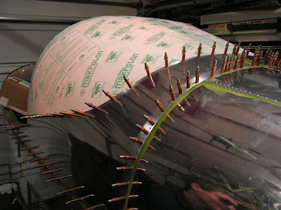
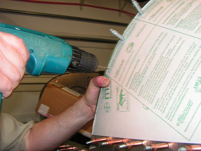
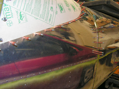
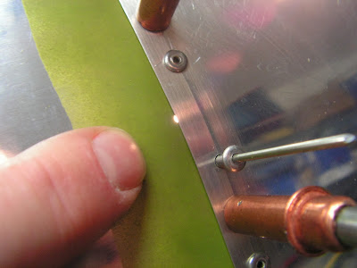
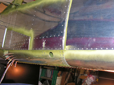
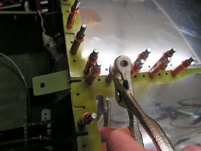
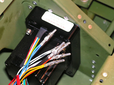
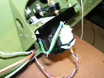
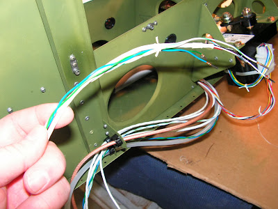
Now that the wiring necessary for attaching the tailcone is done, next time I will start back on the attachment process. But I will leave you with a couple of pictures of the completed tailcone wiring.


Saturday, September 14, 2013

Vans Aircraft RV-12 Airplane Build, Sections 25: Tailcone Attachment (part 1)

Reference: pages 25-02; 1.0 hours

This entry starts the attachment of the tailcone onto the RV-12. Couple of thinks I learned are: first make sure to bend the tailcone tabs up and out. I bent them the wrong way the first time. Also the angel of the bends seam pretty exact, but the main goal is to have them lay flat against the forward skin with out causing the tailcone skin to wrinkle or pucker.

NOTE: Remove empennage assemblies from the Tailcone Assembly, refer the Section 11-Empennage Attachment.

Builder's note: I have not attached the tail feather as of yet.

Step 1: Retrieve the bending tool that was fabricated on Page 17-06.

Builder's note: Or make a new one if you can't find the old one!

Step 2: Bend the forward tabs on the F-1278 TOp Skin, F-1279-L & -R Uper Skins per the angular dimensions given in figure 1. All tabs bent outboard.


Step 3: Mark, then prepare the Shoulder Strap Lugs by removing the hatched areas called out in figure 2 on page 25-02 of the RV-12 aircraft plans.


That's it for this entry.

Friday, September 13, 2013

Vans Aircraft RV-12 Airplane Build, Sections 44A: Autopilot Servos (part 3)

Reference: pages 44A-04, pages 44A-06; 2.75 hours

Today will all but finish up the installation of the Auto Pilot servos into the RV-12 aircraft. The only remaining thing after today will be log book entires. Since I don't have the log books the entries will have to wait.

Step 1: Insert the bolt that will attach the Pitch Servo Pushrod Assembly to the arm of the IF DYNON AP SV32 Autopilot Servo.


Step 2: Attach the autopilot servo to the F-1215-R Seat Rib and F-1269 Servo Doubler using the hardware called out in Figure 1 and Loctite 242 or equivalent medium thread locker.


Step 3: Connect the Pitch Servo Pushrod Assembly to the tab on the WD-1210 Control Column and the IF DYNON AP SV32 Autopilot Servo arm. See Figure 1 on page 44A-04 of the RV-12 aircraft plans.

Step 4: Connect the spade terminal on the red wire coming from the Molex connector mating to the IF DYNON AP SV32 Autopilot Servo with the appropriate gender spade connector coming from the ES-00103 Noise Filter. See Figures 2 and 3.

Connect the spade terminal on the red wire coming from the WH-0045 Options Harness to the remaining spade connector on the noise filter.Connect the ring terminal on the noise filter ground wire to the F-1215-R Seat Rib. See Figures 2 and 3.


Step 5: Mate the Molex connector on the IF DYNON AP SV32 Autopilot Servo to the Molex Harness and WH-00046 Fuselage Harness as shown in Figures 1 and 3.

If your aircraft does not have a Molex connector on the autopilot servo wires go to Page 44A-06, Step 4 for instructions to reconfigure your harness to mate to the servo Molex connector. Reference: goto page 44A-06

NOTE: DO NOT cut the male spade connector off the red WH-RV12-OPTIONAL harness and WH-B170 Autopilot Harness wires.

Step 4: Cut the four female spade connectors off the ends of the WH-RV12-OPTIONAL harness wires and WH-B170 Autopilot Harness wires. (Each spade connector is crimped onto two wires. These spade connectors were installed per Page 31-09, Step 8.) Cut the male spade connector off the ORN WH-RV12-OPTIONAL harness and WH-B170 Autopilot Harness wires. Cut the male spade connector off the WHT/BLK WH-RV12-OPTIONAL harness and WH-B170 Autopilot Harness wires.


NOTE: See chapter 5W Open Barrel Crimp.

Step 5: Strip the ends of the twelve WH-RV12-OPTIONAL/WH-B170 Autopilot Harness wires. Twist together the stripped ends of each pair of like colored wire and crimp an ES-00003 Molex Pin, .093" (14-20) onto the end of each wire pair.


Step 6: Insert the six WH-RV12-OPTIONAL/WH-B170 Autopilot Harness wire pairs into an ES-00010 Molex Plug, 9 Position as shown in Figure 2. Numbers identifying the wire positions are molded into the back of the connector.


Step 7: Cut a piece of 22 gauge wire 3 1/2 inches long. Strip one end and crimp on an ES-00005 Molex Pin, .093" (18-22). Strip the other end and crimp on an ES 421-108 Female Spade Connector.


Step 8: Insert the Molex pin end of the wire into position 6 of the ES-00010 Molex Plug, 9 Position as shown in Figure 2. Continue the installation process by returning to Page 44A-04, Step 6.


This completes page 44A-06.

Reference: Back to page 44A-04.


Step 6: Install a tie-wrap around the IF DYNON AP SV32 Autopilot Servo to secure the Molex connectors and ES-00103 Noise Filter as shown in Figures 1 and 3. Tie-wrap wires as required to prevent wires from chafing.


Step 7: Check controls for full range of motion.

This completes page 44A-04. THis section is all but done. Page 44A-06 deals with installing the autopilot disconnect switch which is already installed in section 42D. It also deals with logbook entries and Pilot Operating Handbook entries that willneed to be done later.

Tuesday, September 10, 2013

Vans Aircraft RV-12 Airplane Build, Sections 44A: Autopilot Servos (part 2)

Reference: pages 44A-03, pages 44A-06; 1.5 hours

Today I will start installing the autopilot servo into the RV-12 aircraft. I have to say not having the tailcone in place makes this job much easier as opposed to crawling into the baggage compartment.

Step 1: Cut all the wires coming from both IF DYNON AP SV32 Autopilot Servos to be 7 inches long.

NOTE: See chapter 5W Open Barrel Crimp. For a good example of an open barrel crimp see the WH-00045 Options Harness.

Step 2: Strip the ends of all the wires coming from both IF DYNON AP SV32 Autopilot Servos and crimp an ES-00006 Molex Socket, .093" (18-22) onto the end of each wire.


Step 3: Insert the wires from each IF DYNON AP SV32 Autopilot Servo into an ES-00009 Molex Receptacle, 9 Position (.093" Sockets) as shown in Figure 1 on page 44A-06. Numbers identifying the wire positions are molded into the back of the connector.


Step 4: Connect the Roll Servo Pushrod Assembly to the IF DYNON AP SV32 Autopilot Servo as shown in Figure 2.


Step 5: Mate the Molex connector on the IF DYNON AP SV32 Autopilot Servo to the Molex connector on the WH-00045 Options Harness as shown in Figure 2.

If your aircraft does not have a Molex connector on the autopilot servo wires go to Page 44A-06, Step 1 for instructions to reconfigure your harness to mate to the servo Molex connector.

Reference 44A-06

Step 1: Cut the spade connectors off the ends of the seven WH-B170 Autopilot Harness wires. (These spade connectors were installed per Page 31-09, Step 11.)

Builder's Note: I hate cutting off perfectly good spade connectors!


NOTE: See chapter 5W Open Barrel Crimp.

Step 2: Strip the ends of the seven WH-B170 Autopilot Harness wires and crimp an ES-00005 Molex Pin, .093" (18-22) onto the end of each wire.


Step 3: Insert the seven WH-B170 Autopilot Harness wires into an ES-00010 Molex Plug, 9 Position as shown in Figure 1. Numbers identifying the wire positions are molded into the back of the connector. Continue the installation process by returning to Page 44A-03, Step 6.


Reference back to page 44A-03

Step 6: Bolt the IF DYNON AP SV32 Autopilot Servo to the F-1286B-L & -R Servo Angles using Loctite 242 or equivalent medium thread locker. See Figure 2.


Step 7: Install a tie-wrap around the IF DYNON AP SV32 Autopilot Servo to secure the Molex connectors as shown in Figure 2.


Step 8: Remove the hardware holding the left Flaperon Pushrod assembly to the WD-1215-L Flaperon Torque Arm.

Step 9: Using new hardware provided, attach the Roll Servo Pushrod Assembly and Flaperon Pushrod Assembly to the WD-1215-L Flaperon Torque Arm. See Figure 2.


Step 10: Reinstall the bolt and nut used to attach the right Flaperon Pushrod Assembly to the WD-1215-R Flaperon Torque Arm for the orientation shown in Figure 2.


This completes today's work on the RV_12. Next time I will continue the instllation of the autopilot servos.

Monday, September 9, 2013

Vans Aircraft RV-12 Airplane Build, Sections 44A: Autopilot Servos (part 1)

Reference: pages 44A-02; 1.5 hours

Step 1: Cut the F-1291 Roll Servo Pushrod and the F-1292 Pitch Servo Pushrod from AT6-058X5/16 Tube. Drill and tap the ends of each pushrod. See figure 1 on page 44A-02 for the drill and tap size.


Step 2: Assemble the F-1291 Roll Servo Pushrod and hardware as shown in Figure 2 to make the Roll Servo Pushrod Assembly.


Step 3: Assemble the F-1292 Pitch Servo Pushrod and hardware as shown in Figure 3 to make the Pitch Servo Pushrod Assembly.


Steps 4 & 5: These are NA as they deal with removing the seat ramp cover and bulkhead covers. These have not installed.

This completes this entry and fabrication of the two Servo push rods.