Today find me working on two different projects. The first is catching a task my EAA Tech Counselor gave me to do. He suggested I fill any holes in the wing spars with rivets. I looked back over the RV-12 wing plans and didn't find any mention of filling these holes, but it seems like a good idea.
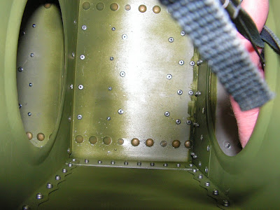
The first picture is taken inside the first bay of the wing and shows the holes I will fill plus the fact I need to vacuum out the wing again.

Builder's note: This next picture shows some rivet holes in the front of the left wing spar that I will fill.

These next two pictures show the holes filled with rivets.

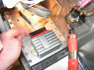
With the riveting project done it is time to move back to Plumbing the Rotax engine on the RV-12 airplane.
Reference: 46-14
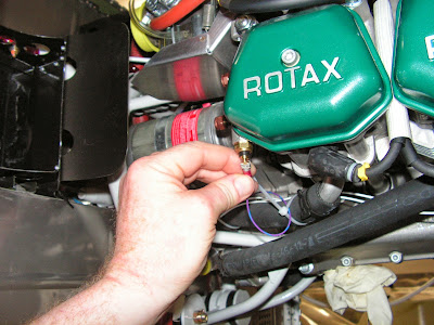
Step 6: Find the WH-E749 (PRP/BLU) CHT 2 (RIGHT) Wire and route it forward along the Rotax Oil Pressure wires. Cut the wire to length, strip the end, crimp on the called out connector and attach it to the terminal post.
Builder's note: The newest plans revision show the CHT probes on the top of the cylinders not at the bottom like my engine.
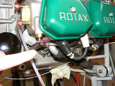
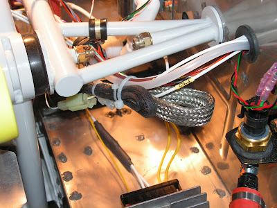
Step 7: Find the WH-E754 (WHT/BRN) Oil Temperature Wire, separate it from the bundle and route it forward under the left side, and secure the wire with tie wraps. Cut the wire to length, strip the end, crimp on the called out connector and attach it to the terminal post near the base of the oil filter.

Builder's note: I can't bring myself to use wire ties on the oil pushrod tubes so Adel clamps will be used in the future to replace the tie wraps.
Step 8: Find the WH-E753 (PRP/YLW)CHT 2 (L) Wire, separate it from the bundle and route it forward along the same path as the Oi Temperature Wire. Cut the wire to length, strip the end, crimp on the called out connector and attach it to the terminal post.
This completes page 46-14. Except for Step 4, the selecting the Oil Pressure sensor in the Skyview EFIS system.
Reference: Page 46-15
Step 1: Locate the Generator to Rectifier Regulator cable (hereafter referred to as the regulator cable) which is a shielded two conductor cable whose diameter is 0.4 in. and is approximately 26 in. long. The regulator cable exits the upper left side of the generator and has two spade connectors attached to yellow wires at the opposite end.

Step 2: Route the regulator cable to the 965 347 Rectifier Regulator.
Step 3: Remove the 965 335 Connector Housing (supplied with the engine) from the 965 335 Rectifier Regulator.

Step 4: Insert the two spade connectors on the end of the regulator cable into the indicated 965 335 Connector Housing locations. It does not matter which of the two spade connector goes where. Check that the connectors are locked in place by gently tugging on each wire.
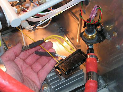
Step 5: Insert the 965 335 Connector Housing back into the 965 347 Rectifier Regulator.
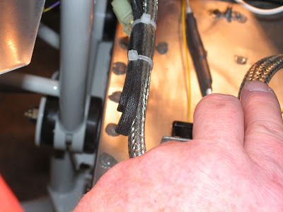
Step 6: Tie wrap the excess regulator cable to the main wire bundle at suitable points between the firewall and the cushioned clamp attached to the WD-1221 Engine Mount Standoff. Leave a generous radius where the regulator cable reverses direction. Regulator cable minimum bend radius is 3/4 in.
Step 7: Insert the WH-E758 (BLK) and WH-E757 (WHT/GRN) wires coming from the WH-00063 Rotax Fwl Fwd Wiring Harness into the back of the ROTAX 265 252 female two pole connector housing as shown in Figure 1 on page 46-15. Their position in the connector does not matter.

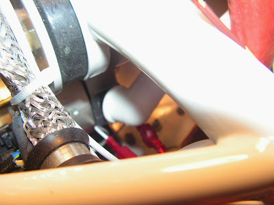
Step 8: Locate the Male Trigger Coil Assembly connector on the engine. Determine the length necessary to reach the ROTAX 265 252 female two pole connector housing then make a service loop from the excess cable and tie wrap it to the regulator cable. Connect the male and female connectors.
This completes page 46-15.
Reference: Page 46-16.
Step 1: Slide an insulated boot over the end of the WH-P155 (WHT) Starter Power Cable then attach the ring terminal to the power stud on the starter using the hardware called out in Figure 1 on page 46-16 of the RV-12 plans. Torque the 6mm hex nut to 35 in-lbs. Slide the insulated boot into place.

Step 2: Use the hardware shown in Figure 1 to connect the WH-P151 (WHT) Engine Ground Cable to the remaining lug on the starter.

This completes page 46-16 and today's entry. Enjoy!

