Showing posts with label RV12 Service Bulletin. Show all posts

Tuesday, July 29, 2014

Vans Aircraft RV-12 Airplane Build, Section 42C: Skyview Update (part 9) & Service Bulletin 13-12-12

Reference for this entry: pages 42C-09, Service Bulletin 13-12-12; 6.0 hours

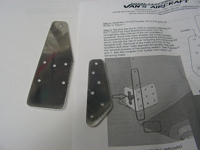
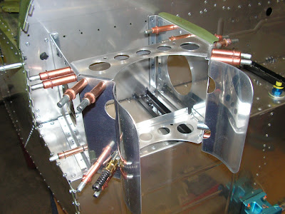
Today I will be working on the new ADAHRS stiffener for the Dynon Skyview. It goes in the tail cone of the RV-12 airplane just infront of the AHARS modual. Also this the day I choice to work on the SB 13-12-12 or sealing the avionics bay on the RV-12.


Reference: Page 42C-09:

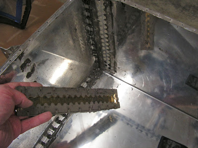
Step 1: Counting from the aft most rivet remove the tenth rivet from the F-1283C J Stiffener. then cleco the stiffener to the J Stiffener wehere the rivet was just removed.


Step 2: Align the ADAHRS Stiffener perpendiculary to the J-Stiffener.


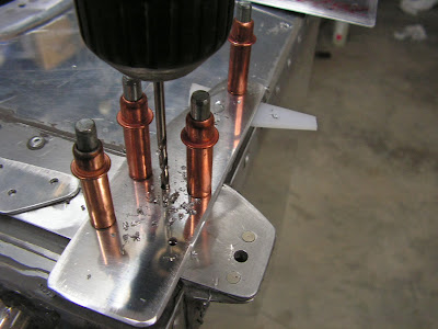
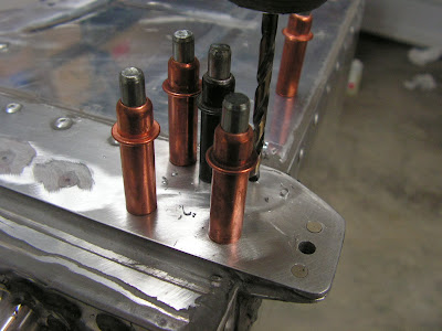
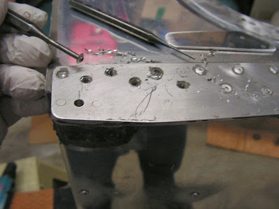
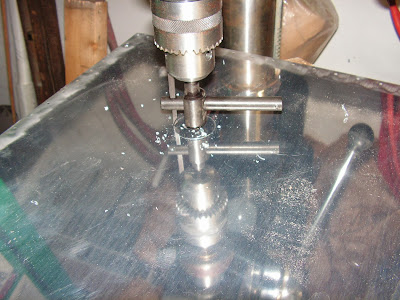
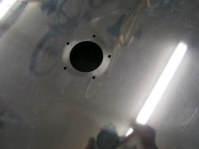
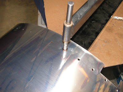
Step 3: Match-Drill #30 the holes in the Stiffener into the Top Skin . Deburr all of the holes.


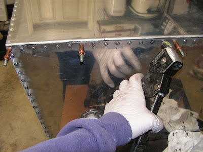
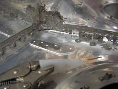
Step 4: Blind rivet the ADAHRS Stiffener to the J_Stiffener and Top Skin from outside of the fuselage.

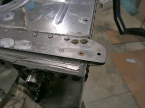
This completes Page 42C-09 and the installation of the ADAHRS Stiffener.

Reference: SB 13-12-12

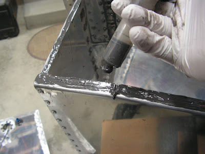
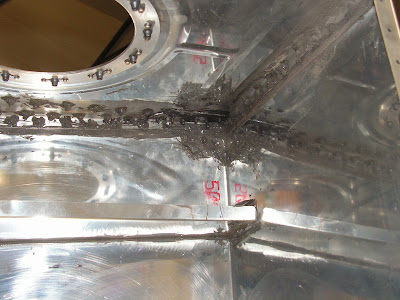
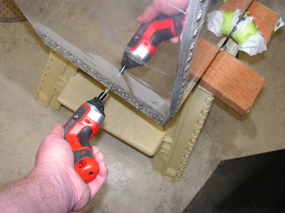
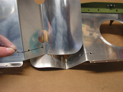
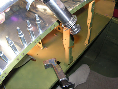
Step 1. Remove, if/as required, the F-1240 Upper Forward Fuselage Skin and apply a release agent to the area of the F-1240 which mates to the F-1201H Upper Fwd Fuse Doubler.


Builder's note: I put aluminum tape (electrical would have been better) on the openings on the sides panels so I could seal these as well.

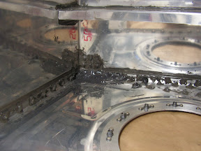
Step 2. Apply approx. 1/16 diameter bead of sealant (see above) to the entire length of the F-1201H Upper Fwd Fuse Doubler.

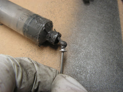
Builder's note: The service bulletin calls out using Black silicon or equilvalent. So I used fuel sealant with good results.

Step 3. Install (or re-install) the F-1240 Upper Forward Fuselage Skin and allow sealant to cure.


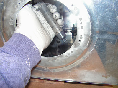
During this time I also sealed the steps to the fuselage.


That's it for today's work on the RV-12 airplane by Van's Aircraft.

Monday, July 14, 2014

Vans Aircraft RV-12 Airplane Build, Notification 14-06-30 VA-215 Oil Return Hose Re-Route

Reference for this entry: Notification 14-06-30; 1.0 hours

This is the service notice I refered to a couple of entries earlier for the RV-12 airplane. While not technically a Service Bulletin, it is still important.

Step 1: Remove tie-wraps that may be holding the VA-213 Oil Supply Hose and VA-215 Oil Return Hose together.

NOTE: Disconnecting the VA-213 Oil Supply Hose should not be necessary to comply with this Notification. Doing so will require an oil purge. See the Rotax manual for further information.

Step 2: Inspect the VA-213 Oil Supply Hose and VA-215 Oil Return Hose for interference with the firewall structure (F-1257 Rudder Pedal Channel or corner edge of the shelf) and possible damage. See Figure 1 of notice. If only the fire sleeve has been damaged by the channel the hose assembly may be returned to service by sealing the hole with high temp RTV. If the channel has worn into the oil hose the hose assembly must be replaced.

Step 3: Disconnect the VA-215 Oil Return Hose from the oil tank. Do not disconnect the VA-213 Oil Supply Hose.


Step 4: Re-Route the VA-215 Oil Return Hose between the WD-1220 Engine Mount and WD-1221 Engine Mount Standoff.


Step 5: Re-Connect the VA-215 Oil Return Hose to the oil tank.

Step 6: Tie-Wrap the VA-213 Oil Supply Hose and VA-215 Oil Return Hose together as shown in Figure 3.

Step 7: Add RTV between the VA-213 Oil Supply Hose and the cabin heat push pull cable. See Figure 3.


Step 8: Add RTV between the VA-215 Oil Return Hose and the WD-1221 Engine Mount Standoff. See Figure 4.


Step 9: Make a logbook entry showing compliance with this notification.

This completes Notification 14-06-30.

Monday, February 17, 2014

Vans Aircraft RV-12 Airplane Build, Section 37: Fuel Tank (part 8); new fuel tank gauge; new tank vent kit

Reference: pages 37B-03, 37-06, Service Bulletin 13-12-19; 2.25 hours

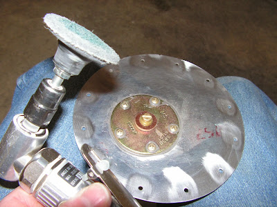
Step 19: Reinstall the Sender Plate with fuel tank sealant using the hardware called out and two new lock washers that are supplied by Van's Aircraft. Use a 1/16 inch thick layer of sealant between the plate and tank bulkhead. Tighten screws just enough to cause sealant to bulge evenly from underneath the perimeter of the plate.
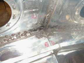


Rechecked the continuity of the sender unit using a Ohm meter and everything worked within tolerances.

Reference: page 37-07

Step 5 - 8: Installed the nutplates that hold the fuel filler neck to the fuselage skin per Van's Aircrafts instructions.


So the RV-12 fuel tank is assembled and I'm going to let it sit a few weeks before pressure testing it. But there are plenty of other projects to work on in the meantime. The plan is to install the empennage onto the RV-12 airplane kit and then finish rigging the aircraft controls.

Sunday, February 16, 2014

Vans Aircraft RV-12 Airplane Build, Section 37: Fuel Tank (part 7); new fuel tank gauge; new tank vent kit

Reference: pages 37B-03, 37-06, Service Bulletin 13-12-19; 3.5 hours

Today and tomorrow will finish up most of the work for the RV-12's fuel tank. I am installing the new vent kit which is not required but seemed like a good idea since the fuel tank is disassembled for the Service Bulletin work. In looking over the plan revisions this vent is now part of the regular kit produced by Van's Aircraft.
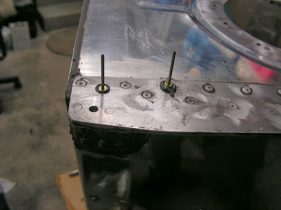
Reference: 37B-03

Step 1: Removed Res Sender Plate previously.

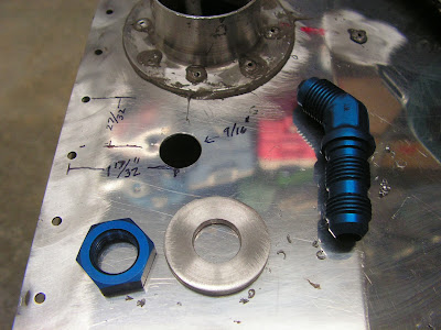
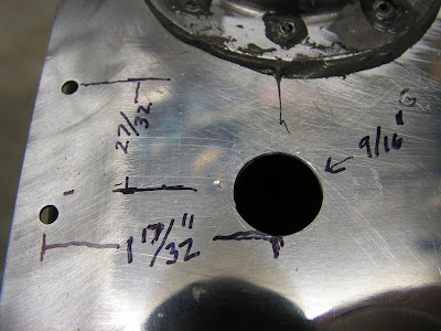
Step 2: Using the template found on page 37B-03 (which was not to scale) measure and drill the hole in the fuel tank top. Deburr the hole.


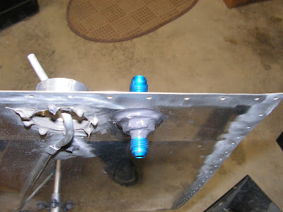
Step 3: Finish installing the fuel fitting as out lined on page 37-05 step 5.

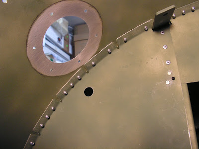
Step 4: Using the template supplied by Van's aircraft, drill the hole in the Baggage Bulkhead.


Reference page 37-06

Step 4: Install the new mechanical Fuel Gauge.

Sorry no pictures.

Step 5; Install the fluid fitting for the new RV-12 fuel tank vent.


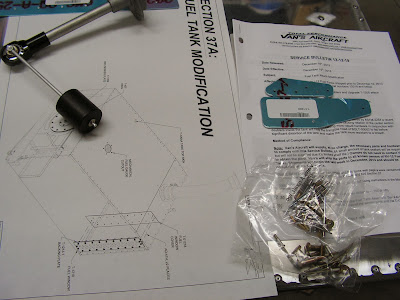
Service Bulletin 13-12-19

Step 17: Reconnected the fuel return line to the fitting on the bottom of the fuel tank.

Reinstalled the fuel tank top after completing all internal work.


Turned tank upside down and put a dab of sealant on each new rivet.


I'm letting the fuel tank sit upside down overnight before completing the job of installing the sender unit plate.

Sunday, February 9, 2014

Vans Aircraft RV-12 Airplane Build, Section 37: Fuel Tank (part 6) & Fuel tank Service Bulletin 13-12-19 and new fuel tank gauge

Reference: Service Bulletin 13-12-19; 3.0 hours

Today's work is the continuation of the fuel tank update for the RV-12 aircraft I am building. On other mod that Van's Aircraft is offering is a RV12 Fuel Tank Vent Modification Section 37B. It's not required but does away with the hole in the fuel tank cap and allows fuel to dump over board do to expansion in the heat. I will be installing it at a future date.

Step 9: Cleco the T-01220A doubler to the tank and match drill the tank with a #30 drill bit. The top hole must be supported with a 1/8" spacer before drilling. After deburring the doubler is clecoed to the inside of the fuel tank.


Step 10: Final drill #19 the three hole specified by Van's Aircraft in the service bulletin.


Step 11: The lower screw hole is then countersunk for the head of a AN509-8R10 machine screw.

Step 12: Deburr the tank and doublers and clean all of the chips and debris out of the fuel tank.

Step 13: Add a thin layer of fuel tank sealant between the fuel tank and the doublers. Rivet the doublers into place.


Step 14: Install the screws to the doubler as directed in the service bulletin.


Step 15: Install all remaining rivets that were removed

Step 16: Apply sealant to the interior of the doublers and the fwd lower tank corners.


Also see page 37-03 for more information. on the above steps. That's all for this entry. But the fuel tank is the gift that keeps giving so there is more to come on the RV-12 airplane fuel tank.

Saturday, February 8, 2014

Vans Aircraft RV-12 Airplane Build, Section 37: Fuel Tank (part 5) & Fuel tank Service Bulletin 13-12-19 and new fuel tank gauge

Reference: Service Bulletin 13-12-19, Page 37A-02, 37A-02-03; 9.0 hours

Being snowed in, this seems like a good time to start the fuel tank revisions and updates on the RV-12 airplane.


Steps 1 & 2: Get copies of the newest revision of section 37 and the Maintenance Manual. Remove the fuel tank (if installed.)

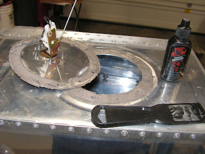
Step 3: Remove the Sender plate. I read that lubricating the plastic putty knife makes it slider easier under the plate and it does help.


Step 4: Separate the T-01220 doublers.


Builder's note: Because I am also removing the fuel sight window and replacing it with the mechanic gauge option I decided to remove the entire top of the fuel tank. It is not required but I am glad I did.

Step 5: Didn't need to remove the two nutplate because of the unlimited access to the inside of the tank with the top removed. I did remove the rivets that are common to the two new doublers.


Step 6, 7 & 8: Disconnected the fuel return line form the bottom inside corner of the fuel tank. Used a scrap piece of UMHW plastic to scrap the old sealant from the area the new doublers will fit. Testing fitting the new doublers to ensure they fit properly. Also radiused the edges that fit in the bend radii of the tank bulkhead.


Reference 37A-02

Step 1: Removed the Fuel Window from the tank.


Reference: 37A-03

Steps 1 - 3: Using the provided template marked and cut the hole for the optional fuel tank gauge. (First time I have used a flybar cutter in 10 years of owning one.) Also marked and drilled the mounting bolt holes in the top of the fuel tank.


It's been a long day so I'm going to call it. Tomorrow I will continue on the service bulletin for the RV-12 fuel tank.

Friday, July 12, 2013

Vans Aircraft RV-12 Airplane Build, Section 29A FWD Upper Fuselage (part 4)

Reference: page 29A-06 and SB 13-04-05; 7.0 hours

Van's Aircraft issued a service bulletin because of cracks developing in the Oil Tank Bracket on some airplanes. They did send the parts out with the notice which is great customer service. So with this posting I will continue with the Upper fuselage and installing the SB 13-04-05 service bulletin.

Reference: SB 13-04-05

Steps 1-5 Do not apply as this RV12 is still under construction.

Step 6: Using the dimensions in Figure 4 (from the service bullitin) layout then drill #30 the hole pattern shown into the F-1201E-L & -R Brackets.


Step 7: Deburr the edges of the F-1201GMOD rib. Draw a centerline on the four forward facing rib flanges. Orient the rib, flanges facing up as shown in Figure 4 so that the centerlines drawn on the flanges are centered on the holes drilled in the previous step. Match-Drill #30 the holes in the F-1201E-L & -R into the rib. Remove and Deburr the rib. Prime the rib if desired. Rivet the rib to the brackets using the rivets called out in Figure 4.


These next three steps will be completed after I get an engine and a log book!

Step 8: Re-install the oil tank and battery. Add oil to the system. Re-install the lower and upper cowlings.

Step 9: Complete Rotax SI-912-018 oil system purge procedure.

Step 10: Make a logbook entry indicating compliance with this Service Bulletin.

Reference: page 29A-06

Step 1: Dimple the three holes in each Oil Tank Side Bracket that will receive flush fasteners as called out by Van's Aircraft.
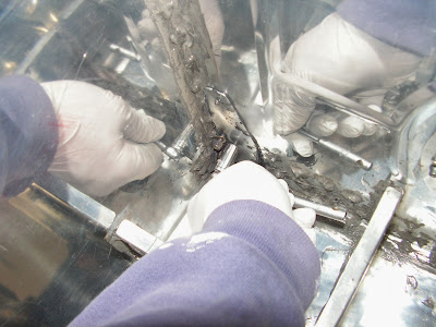


Step 2: Rivet the Oil Tank Side Brackets to the Firewall Upper. Rivet the Battery Mount Brace to the firewall upper.


Step 3: Rivet the Battery Mount Brace, Battery Mount Angles and Oil Reservoir Brace to the Oil Tank Side Brackets.
Builder's note: This is also when I installed the new SB bracket


Step 4: Cover the head of each rivet on the firewall with a thin layer of fuel tank sealant.


Step 5: Make the Clip from provided AS3-025 aluminum as shown in figure 2 on page 29A-06 of the RV12 plans. Match-drill #40 to the F-1240B Cover Plate. Test fit the clip to the fuselage to determine which side goes up then deburr and dimple the rivet and screw holes in the clip and the cover plate then rivet the clip to the cover plate using the rivets called out.


Step 6: Carefully curve the forward edge by hand. The upper forward fuseage skin should be curved enough that the forward edge presses against the Upper Forward Doubler when installed.


Step 7: Final-drill #19 then dimple the holes in the Upper Forward Fuselage Skin.


Step 8: Screw the Upper Forward Fuselage Skin to the F-1201A Assembly, Fuselage Side Skins and the Canopy Ribs.

Screw the F-1240B Assembly to the upper forward fuselage skin.


Step 9: Dimple the nutplates called out and the rivet locations in the Panel Attach Strips Rivet the nutplates to the panel attach strips.


Step 10: Start from the inboard and work out clecoing then riveting the Panel Attach Strips to the Upper Forward Fuselage Skin.


This completes page 29A-06 and the service bullitin SB 13-04-05 for the RV-12 aircraft. So long until next time.