Saturday, June 29, 2013

Vans Aircraft RV-12 Airplane Build, Section 29A FWD Upper Fuselage (part 2)

Reference: page 29A-03; 4.5 hours

This is the second installment for the construction of the Upper Fuselage on my RV-12 aircraft. There is a GOTCHA that I didn't catch until sometime later. It was fixable but the time to catch it is now!!!

GOTCHA Here it is in all it's glory. This screw hole is for a #8 screw. Dimple it before installing the upper firewall on the plane! There is one hole on each side of the aircraft. I didn't and had to build a special dimpling die to fix it later.


Step 1: Smear a thin layer of fuel tank sealer on the uper surface of the bottom flange of the F-1201A Firewall Upper.


Rivet the Assembly to the fuselage assembly.

Step 2: Match-Drill #30 the Mid Cowl Hinges to the Firewall Spacers and Side Skins.


Step 3: Cleco then rivet the two Mid Cowl Hinges to the Firewall Spacers and Side Skins (with the manufactured head on the exterior).


Step 4: Dimple the nutplate rivet hoes in the nutpaltes, then rivet to the F-1201A Assembly and fueslage assembly as shown in figure 1 on page 29A-03 of the RV 12 aircraft plans.

Step 5: Cleco then rivet the Forward Skin Stiffeners to the F-1201A Assembly and the Fuselage Side Skins.


Step 6: Actually completed on 7/10/13) Fill the #11 tooling holes in the Firewall Upper with Firewall Sealant. Add a bead of Firewall Sealant around the perimeter of the firewall parts. Use a Popsicle stick to form a smooth fillet. Make sure all pages from the bend relief notches along the flange and in the corners are fully sealed. Use a light on the forward side of the firewall to help verify that the full perimeter of the firewall is fully sealed.

Builder's note: Firewall sealant is just strange stuff it is not like fuel tank sealant. It's kind of a cross between black bubble gum and wetsuit material. It is NOT the same as fuel tank sealant (which burns readily when exposed to a flame source even when dry.) Firewall Sealant skins over very fast and has a short work handling time.

I cleaned the primer of of the fuselage skins with MEK and added two stripes of electrical tape keep the edges clean. I purchased the pint can of Firewall Sealant and used a plastic syringe to create the fillet.


This completes page 29A-03. Please don't forget about dimpling those two screw holes! And with that I will leave you to ponder Firewall Sealant.

Wednesday, June 26, 2013

Vans Aircraft RV-12 Airplane Build, Section 29A FWD Upper Fuselage (part 1)

Reference: page 29A-02; 5.0 hours

This entry starts the forward upper fuselage on the RV-12 aircraft. During the construction I am updating to the new Skyview EFIS system so there are a number of changes between the original section 29 and this new section 29A. Also there is a service bulletin regarding the oil reservoir tank mount, but more on that later. I also ran into a GOTCHA on the plans and called Van's Aircraft about it. It deals with the upper cowl hinges the plans tell you to mount them a certain wal but this is not possible. There are pictures and more notes listed below.

Step 1: Mark two lengths of AN257-P3 piano hinge to make the Mid Cowl Hinges per the dimensions in Figure 1 on page 29A-02 of the RV12 plans. Remove the hinge pin then cut the hinge to length. Set aside the hinge pin and unused halves of the piano hinge for the cowl installation.


Step 2: Make the Upper Cowl Hinges from AN257-P3 piano hinge per the dimensions in Figure 2. Remove the hinge pin before cutting the parts to length. Set aside the hinge pin and unused halves of the piano hinge for cowl instillation.

Step 3: Dimple the Firewall Spacers and corresponding screw and rivet holes in the Firewall Upper. Dimple the rivet holes locations in the corresponding nutplates. Cleco the firewall spacers and nutplates to the lower flange of the firewall upper. Rivet the top rivet only as shown in figure 3 on page 29A-02.


Step 4: Machine countersink the nutplate rivet holes in the Upper Fwd Fuse Doubler. Dimple the screw holes in the upper fwd fuse doubler and Firewall Upper for the #8 screws. Cleco then rivet the upper fwd fuse doubler and nutplates to the firewall upper.


Step 5: Clamp the Upper Cowl Hinges to the Upper Fwd Fuse Doubler. Align the lower edge of the upper cowl hinge per the call out. Match-Drill #40 and cleco all the corresponding holes between the upper fwd fuse doubler and the upper cowl hinges. Remove and deburr the parts. Machine countersink the rivet holes in the upper fwd fuse doubler. Cleco then rivet the parts together as shown in Figure 3.

GOTCHA: Here's the deal. If the hinge material for the upper left side is aligned as instructed, one of the end holes is missed (see pictures below.)


Called Van's Aircraft and they said to split the difference so both of the end holes have proper edge clearance. Not a serious problem as long as you catch it before the holes are drilled! See their suggestion pictured below.


Step 6: Dimple then rivet nutplates to the forward and aft sides of the Firewall Upper per the call outs given in figure 3 on page 29A-02.


Step 7: Dimple then rivet nutplates to the Antenna Shelf per the call outs.


Step 8: Rivet the Antenna Shelf to the Firewall Upper.


Step 9: Dimple the rivet holes in the bottom flange of the Firewall Upper per the call outs given on page 29A-02.


This completes page 29A-02 for the RV12 aircraft kitted by Van's Aircraft. Stay tuned in for there is more fun to follow!

Wednesday, June 19, 2013

Vans Aircraft RV-12 Airplane Build, Section 37: Fuel Tank (part 4)

Reference: page 37-05 revision date 11/21/11; 8.0 hours

Today's entry is split between revision 11/21/11 for steps 1-8 and 09/30/09 for steps 9-11. This is due to my kit coming with the older style fuel tank that requires cutting of the fuel tank filler hole. But it is all good!

Step 1: Remove the vinyl protective covering from both sides of the T-1210 Fuel Window, then deburr the edges.

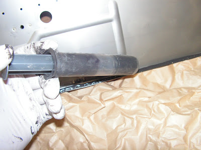
Step 2: Use a toothpick to thinly coat the surface under the head of all the screws that will be used in installing the T-1210 Fuel Window with fuel tank sealant.

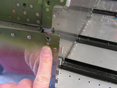
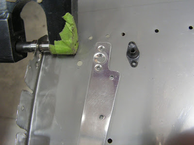
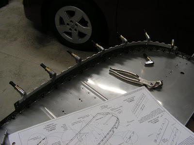
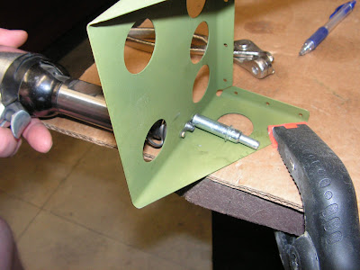
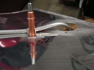
Step 3: Install two screws into the T-1201 Main Tank Skin in the locations called out in Figure 1. Tape over the screw heads to hold them in place then tip the tank on its side with the screw heads against a flat surface.


Step 4: Apply a thin layer of tank sealant along the perimeter of the T-1210 Fuel Window on one side.

Step 5: Apply a thin layer of sealant to the flanges of the T-1213-1 Backing Plate then carefully place the backing plate onto the side of the T-1210 Fuel Window without fuel tank sealant. Reach into the tank and slide the assembly in place over the two screws, then tip the tank upright.


Step 6: 
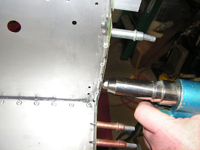
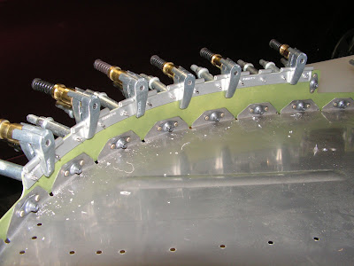
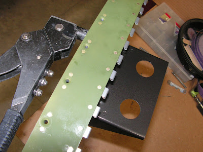
Insert the rest of the screws into the remaining holes attaching the T-1210 Fuel Window. Remove the tape from the two screws used as guides.

Step 7: Install the washers and nuts that attach the T-1210 Fuel Window and T-1213-1 Backing Plate to the T-1201 Main Tank Skin finger tight. Cover the nuts with fuel tank sealant. If using a nut driver to hold the nuts do not tighten the nuts using the handle. Tighten with the shank using fingers only.

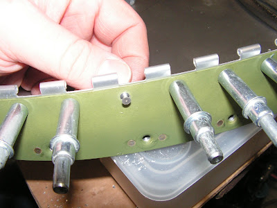
NOTE: Do not attempt to remove any sealant squeezed out at the sight window holes until it is fully cured.

Step 8: Cut the end off of a popsicle stick so it is straight rather than round, then bevel the edge so it can be used as a scraper.After the sealant has cured use this tool to remove any sealant that may have oozed out of the sight window holes.

Reference: page 37-05 revision date 09/30/09; 1.0 hours

The newer RV-12 aircraft kits don't follow these next steps!!!

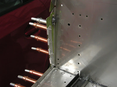
Step 9: Place a blanket or large rag over the inside bottom of the fuel tank to collect drill chips from following steps. Cleco the T-1204A Top Tank Skin to the Fuel Tank Assembly.

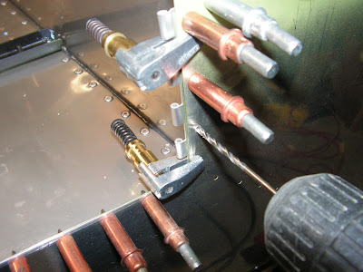
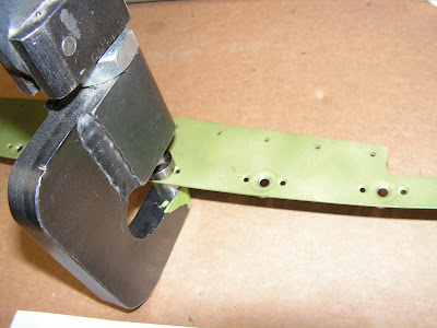
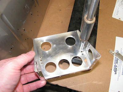
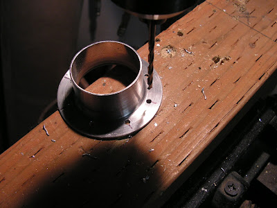
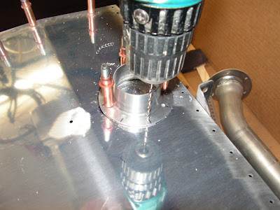
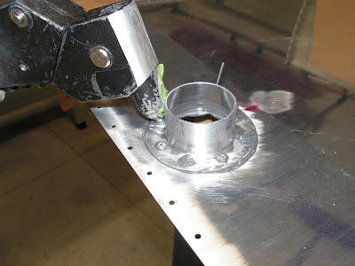
Step 10: Layout and drill #30 a hole pattern in the flange of the T-1204B flange per dimensions given by Van's Aircraft.


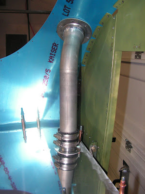
Caution: Avoid deforming the Fuel Neck and Fuel Flange when tightening the hose clamps.

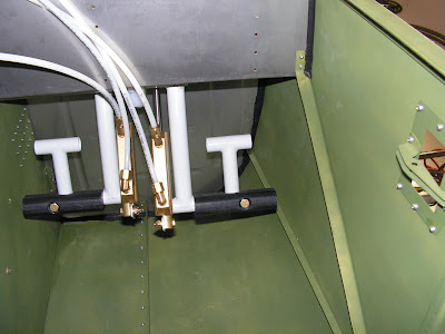
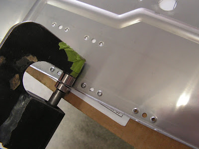
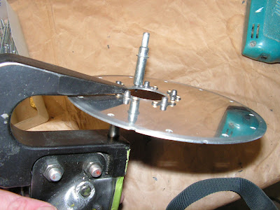
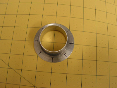
Step 11: Use two hose clamps and the T-1212 Fuel Neck Collar to join the T-1211 Fuel Neck and Flange together per the dimensions call out by Van's Aircraft on page 37-05 of the plans.


This completes page 37-05.

Reference page 37-06 rev 1 dated 02/22/10


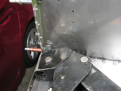
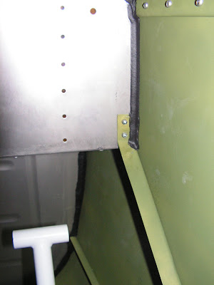
Step 1: Temporarily bolt the Fuel Tank to the Center Section Assembly and the Attach Angle using hardware called out by Van's Aircraft.


Step 2: Center the Filler Neck Assembly on the skin fuel opening. For the best fit of the Filler Neck Assembly(between the Fuel Tank Assembly and the Turtle Deck Skin) it may be necessary to adjust the length by loosening the hose clamps and extending or shortening the assembly. Bend the upper flange of the Fuel Neck as required for at he best fit against the fwd turtle deck skin (small gaps will be filled with fuel tank sealant.)


Step 3: 
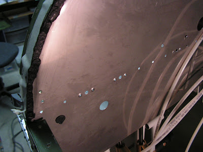
Once satisfed with the postion of the Filler Neck Assembly, match drill #30 the holes in the Fwd Turtle Deck Skin into the flange of the Fuel Neck, cleco as you go. Trace a circle onto the Top Tank Skin around the edge of the Flange. Remove and disassemble the Filler Neck Assembly. Remove the fuel tank from the fuselage.


Step 4: 
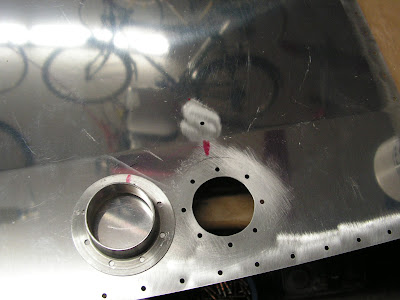
Position the Flange on the Top Tank Skin, centered in the circle from Step 3. Match-drill #30 the holes in the flange into the top tank skin, cleco as you go. Trace a circle onto the Top Tank Skin around the inside of the flange. Mark the rotational position of the flange. Remove the flange and the top tank skin.


Step 5: Remove the material, marked with the inner circle from the Top tank Skin. Deburr the top tank skin and the Fuel Neck. Prime the outside of the fuel neck and Flange ONLY!. Remove any debris from the inside of the fuel tank.


Step 6: 
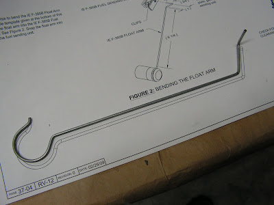
Fabricate two T-1216 Clips per Figure 2 on the RV-12 plans page 37-06.


Step 7: 
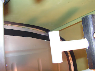
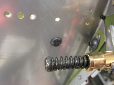
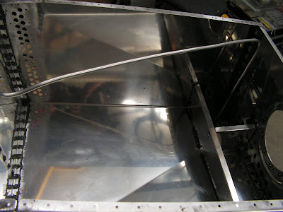
Fabricate the Fuel Return Line per plans. Install a nut and sleeve on one end of the fuel return line and flare that end. From the bulkhead fitting, route the fuel return line with the clops and rivet the clips to the top tank skin.


Step 8: 
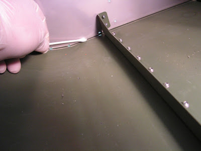
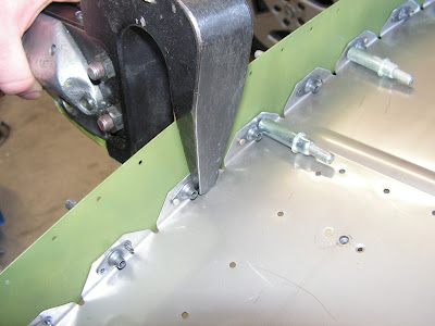
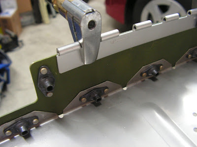
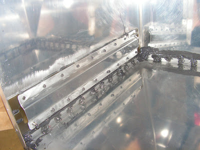
Rivet the Top Tank Skin to the Fuel Tank Assembly per the call-out. Rivet the Flange to the top of the Fuel Tank Assembly. Install the Fuel return line to the bulkhead fitting.

Step 9: Add sealant in any remaining areas, corners cracks and crannies as necessary. Install the Res Sender Plate and Sending Unit with sealant using the hardware called out on Page 37-04. Use 1/16 inch thick layer of sealant between the Res Sender Plate and the Fwd Tank Bulkhead and in place of the IE F-385 Gasket. Tighten screw just enough to cause sealant to bulge evenly from under the perimeter of the sender plate.


This completes page 37-06. Again my plans and kit, because of revisions, is split between two sets of plans. Hopefully this is not too confusing.I'm going to let the tank sit and the sealant to harden before moving on with this section and the pressure test.

Wednesday, June 12, 2013

Vans Aircraft RV-12 Airplane Build, Section 37: Fuel Tank (part 3)

Reference: page 37-04 revision date 11/21/11; 1.0 hours

This is the third installment of the RV12 aircraft fuel tank construction. Please note I'm using revision 11/12/11 of the the plans from Van's Aircraft. Today was a light day of working with the fuel tank sender unit. Enjoy

Step 1: Machine countersink the forward side of the T-1209 Res Sender Plate for nutplate attach rivets.


Step 2: Rivet nutplates to the T-1209 Res Sender Plate as shown in Figure 1.


Step 3: Use a vise to bend the IE F-385B Float Arm per the full scale template given at the bottom of this page. Insert the float arm into the IE F-385B Fuel Sending Unit. See Figure 2 of the RV12 plans. Snap the float arm into the clips on the fuel sending unit.


NOTE: The IE F-385 Gasket in the following step is used only as a spacer to represent the thickness of the fuel tank sealant that will be used for the final assembly. THE GASKET WILL NOT BE USED IN THE FINAL ASSEMBLY.

Step 4: Temporarily attach the T-1209 Res Sender Plate and IE F-385 Gasket and IE F-385B Fuel Sending Unit to the Fuel Tank Assembly as shown in Figure 3. Use the notches to orient the sender plate. The small notch will be offset outboard, of the large notch that will be centered at the bottom. Check for clearance between the T-1208 Baffle and the IE F-385B Float Arm. Check and adjust the float arm for proper travel. See Figure 4. Remove the res sender plate, gasket, and fuel sending unit.


This completes page 37-04 of the RV12 fuel tank construction. Until next time!