Saturday, May 31, 2014

Vans Aircraft RV-12 Airplane Build, Section 38: Cowling (part 6)

Reference for this entry: page 38-08, 38-09; 1.0 hours

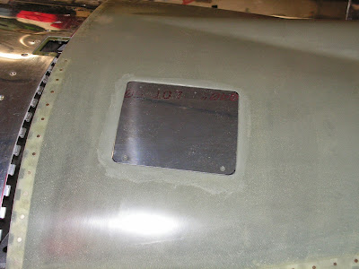
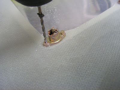
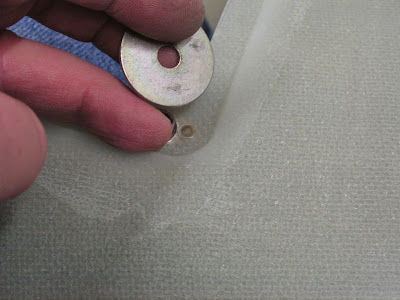
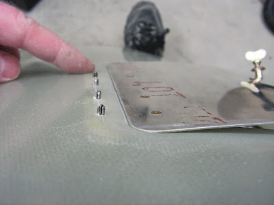
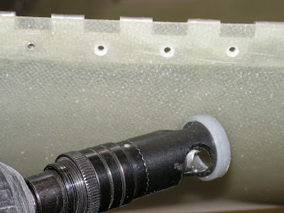
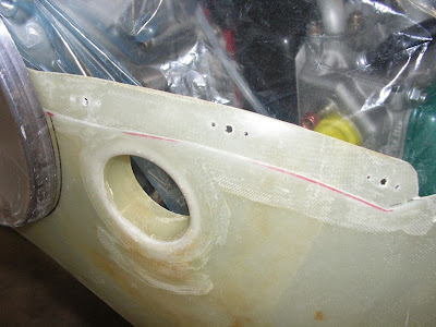
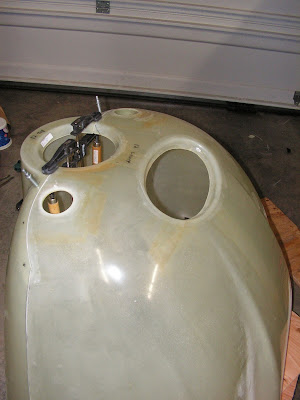
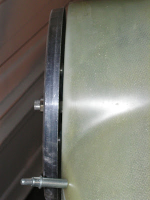
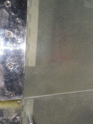
I wasn't real happy with the way the cam receptacles didn't align with the holes in the cowl fiberglass. So I decided to fill these to match the receptacles better. Making a plug out of a plastic pen, I filled the gaps in with epoxy and flox for a better finish.


Reference: Page 38-08

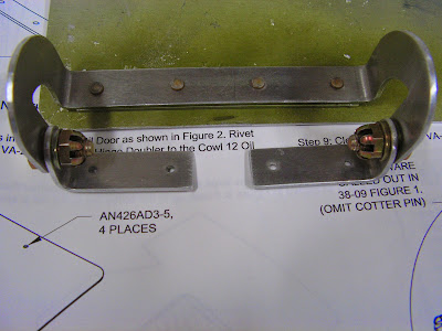
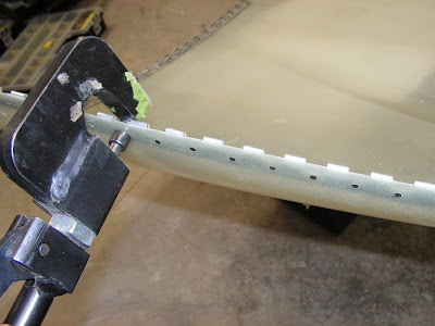
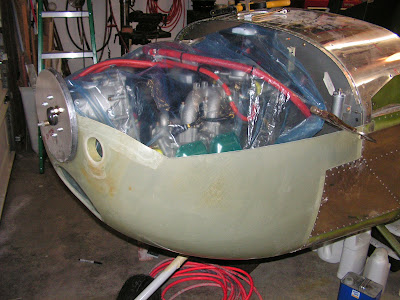
Steps 8 & 9: Remove the cowl door and then rivet the hinge lugs to the top cowl.


This completes page 38-08.

Reference: Page 38-09

Step 1 (final attachment of the Oil Door) will be completed after painting.

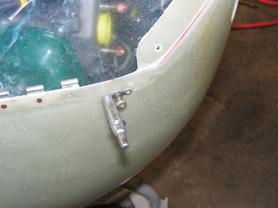
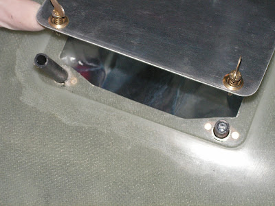
Step 2: Remove the middle nose gear attach bolt indicated in Figure 2 on page 38-09.

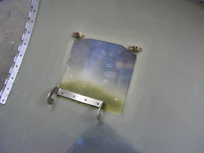
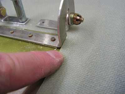
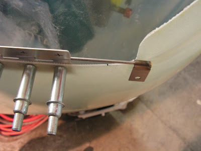
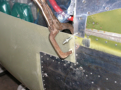
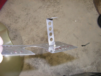
Step 3: Slip the middle nose gear attach bolt through the F-1285B-1 Cowl Close-out Bracket so that the bracket is perpendicular to the bottom of the aircraft with the angled flange sweeping up towards the front.

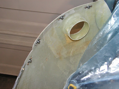
Step 4: Bend the F-1285 Cowl Bottom Close-out to fit the curve of the bottom cowl. Slip the cowl bottom close-out around the WD-1201 Nose Gear Assembly and inside the bottom cowl.Attach the cowl bottom close-out to the F-1285B-1 Cowl Close-out Bracket using the hardware called out in Figure 2. Align the edges of the cowl bottom close-out with the edges of the slot in the bottom of the bottom cowl. Clamp the cowl bottom close-out to the bottom cowl.


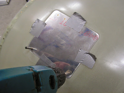
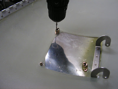
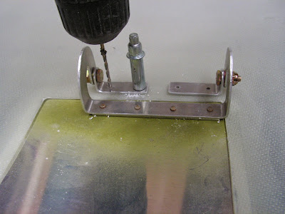
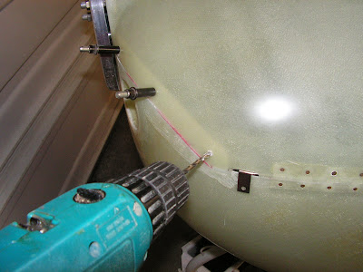
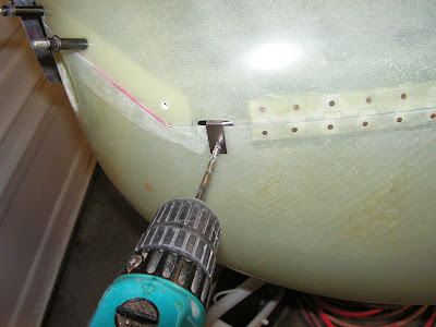
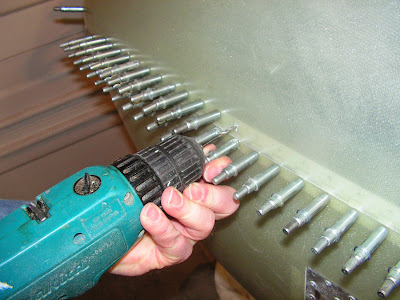
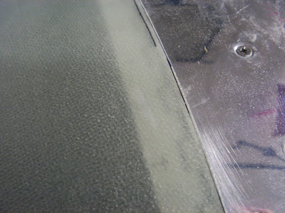
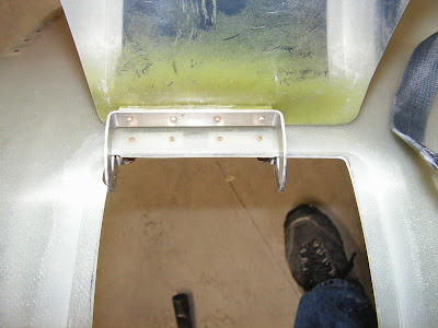
Step 5: Match-Drill #19 the nutplate screw holes into the cowl bottom. Insert a screw in the top of each hole to maintain alignment while drilling.

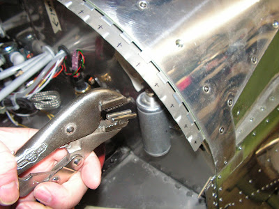
Builder's note: Because the engine is already installed the match drilling was done from underneath the cowl. Note the use of a light to show holes through cowl. Make sure the light is directly above the hole before drilling otherwise shadowing can through the holes out of line.


Thursday, May 29, 2014

Vans Aircraft RV-12 Airplane Build, Section 38: Cowling (part 5)

Reference for this entry: page 38-07, 38-08; 3.5 hours

Today again continues the cowl for the RV-12 including fitting the cowl oil door. I did run into a Builder's Gotcha on the way the door hinges fit.

Step 5: Trim the Cowl Oil Door. Shape the door as needed to fit the recess of the cowl.


This completes page 38-07.

Reference: 38-08

Step 1: Separate the Oil Door Hinge and deburr the hinge parts.


Step 2: Machine countersink the rivet holes in the Oil Door. Then rivet the door together.


Step 3: Using a unibit drill the Oil Door and cowl 1/4 inch. Using the cams the align the camlock recetacles and drill them #40.


Step 4: Final-drill the 1/4" holes in the cowl recess to 1/2".But don't drill the door!

Step 5: Counter sink the rivet holes for the reciptical in the cowl and then rivet these in place.

Builder's note: I used a flat washer so the rivet squeezer dies would clear the cowl door recess when setting the rivets.


Step 6 & 7: Temporarily assemble the hinge hardware on the oil door. Attach the Oil Door to the cowl and align the door. Then drill the hinge lugs into the cowl.


Builder's Gotcha: The hinge hits the cowl opening and need the be trimmed back. Also, my door didn't shut properly because of the difference in door hinge geometry.


To solve this I disassembled the oil door and added an extra spacer between the hinge and door as can be seen in this picture that was taken more recently.


So with the door fit solved I'm going to stop for the day.

Wednesday, May 28, 2014

Vans Aircraft RV-12 Airplane Build, Section 38: Cowling (part 4)

Reference for this entry: page 38-06, 38-07; 5.0 hours

Today will continue the installation of the cowl on the RV-12 airplane with the Rotax engine previously installed.

Reference: Page 38-06

Step 9: Machine counter sink all #40 holes on the top and bottom cowls, except the ones that are on the front of the top cowl and bottom cowl.


Step 10: NA as the hinges were epoxied to the cowl previously.

Step 11 - 14: Rivet the hinges to the top and lower cowl.


This completes page 38-06.

Reference: Page 38-07

Step 1: Install the bottom cowl and the top cowl and final drill #19 the six screw holes at the front of the cowl.


Step 2: Match Drill #19 the hole in the knuckle flange of the Cowl Hinge Pin-Left and Right into the bottom cowl.


Step 3 & 4: Using a #8 screw and nutplate to match drill the rivet holes for the knuckles and the six front nutplates. Next countersink and install the nutplates.


This completes this work period on the RV-12 airplane.


Monday, May 26, 2014

Vans Aircraft RV-12 Airplane Build, Section 38: Cowling (part 3)

Reference for this entry: page 38-05, 38-06, 38-07; 9.0 hours

Today is day three on fitting the cowl to the RV-12 airplane with the Rotax engine installed.

Reference: Page 38-05.

Step 4: Clamp the lower half of the Side Hinges to the upper edge of the lower cowl. The aft edge of the side hinges should be flush with the marks made in step 3.

Step 5: Drill #40 the rivet pattern laid out into the bottom cowl & side Hinges.


Step 6: Using the Cowl Hinge Pin as a guide mark the cowl pin inter section on the bottom cowl.


Step 7: Trim (shorten) the pins until the aft edge of the knuckles alines with the mark on the cowl made in the last step. Bend a jog in the pin so the knuckles lay flat against the bottom cowl surface.


This completes page 38-05.

Reference: page 38-06 Builder's note: THis is were have the engine installed is a pain, since you can't just reach in through the spinner opening to hold the hinges. I use a long pice of wood to hold the hinge against the cowl as it was drilled. Still care must be used so as not mess up the hole in the hinge. This being said I'm glad I had the Rotax hung at this point and would do it this way again.

Step 1 & 2: Install the top cowl & cleco it to the bottom cowl . Checking that the contours of the top cowl match those of the fuselage skins and bottom cowl.

Drill #40 through the top cowl and the Upper Cowl Hinges the most inboard hole and cleco.


Step 3: Mark and Create a notch for the pin knuckles to allow the Pinsto be slipped out without catching on the top or bottom cowl.


Step 4 & 5: Drill #40 then cleco the two remaining holes on each end of the side top and bottom cowl. Then drill and cleco the remaining holes through the top cowl.


Step 6: Hold the forward portion of the Side Hinges tightly against the top cowl. Dril #40 then cleco the forward most hole location and work aft, drilling all top cowl holes to the side hinge rivet hole locations.


Step 7: Starting from the top drill #40 and cleco the remaining holes locations through the Mid Cowl Hinges and bottom cowl.


Step 8: Starting at the bottom drill and colec the remaining holes in the lower cowl hinges.


Reference: Page 38-07

Step 6: Using a unibit drill "starter holes and make the opeing for the Oil Door in the top cowl.


So to finish today's work, decided to roughen the mating surfarce of the cowl hinges and then to epoxy these in place before countersinking the rivet holes. This is the same process I used on the RV-10's cowl but used a Hysol product to do the bonding. At the very least it will make countersink the holes easier as the aluminum will back up the fiberglass.


The hinges need time to setup and it is late so I'm calling it a night.

Sunday, May 25, 2014

Vans Aircraft RV-12 Airplane Build, Section 38: Cowling (part 2)

Reference for this entry: page 38-02, 38-04, 38-05; 6.5 hours

So this entry starts the serious work on the cowling for the RV-12 airplane. Fiberglas isn't scary just different from working with aluminum.

NOTE: Do not remove material beyond the scribe lines or sand the cowl exterior.

Step 1: Trim the top cowl and bottom cowl edges to within 1/8 inch of the scribe lines. Sand to remove the remaining material up to the scribe line. A block with 80 grit paper works well for this.

Step 2: Clean any excess resin that may have cured along the flange joggle on the bottom cowl. Remove abnormal glass and resin buildup from the inside surface of the top cowl. Sand down the corners of the flange on the bottom cowl. This will allow the top cowl and bottom cowl to fit together with little or no mismatch in their outer surfaces.

Step 3: Trim or sand the flange on the bottom cowl to the dimension shown in Figure 2 on page 38-02 of the RV-12 plans.


Step 4: Clamp the top and bottom cowls together as shown in Figure 3. Mark the three hole pattern shown in Figure 3 on both sides of the top cowling. Drill #40 the most inboard hole on each side then cleco these two holes. Remove the clecos and separate the top cowl and bottom cowl.


Step 5: Cut a slot centered on the scoop of the bottom cowl and remove the material up to the scribe lines as shown in Figure 4.


Step 6: Use a unibit to drill a "starter" hole large enough to get a file or sanding block inserted then remove the material up to the scribe lines for the holes shown in Figure 4.

Step 7: Trim the bottom cowl air inlet to within 1/8 inch of the scribe line. Sand to remove the remaining material up to the scribe line as shown in Figure 4.


This completes page 38-02.

Reference: page 38-03.

Step 1: Modify the hinge halves lft over from making the Side Hinges (see page 29-02) as shown in figure 1 on page 38-03. Mark holes but do not drill.


Step 2: Lay out the holes on the Side Hinges as well as the hinge halves remaining from the Upper Cowl Hige and Lower Hinges. But Do Not drill the holes at this time.


Step 3: Install the Mid Cowl Hinge halves with the Mid Cowl pins. Then install the Lower Cowl Hinge halves with the lower cowl hinge pins.


Step5: The cowl hinges should be a continuation of the surface of the adjacent skins. Flute the hinges as needed, especially those that are curves, to bring them into alignment.


Builder's note: The two pictures above show the hinges before fluting which is needed to align them with the skins.


This completes page 38-04.

Reference: 38-05

Builder's note: Before proceeding I protected the finish on the nose gear strut with several layers of masking tape. And covered the engine with a large plastic bag. Also realize fitting the Cowl is trial and error so one may need to take it of several times and sand to final fit.


Step 1: Slide bottom cowl over hinges and clamp to the Mid Hinges so the notch in the cowl bottom aligns with the notch location in the fuselage side skins. Drill #40 the top hole location through the bottm cowl and the mid coal hinges.


Step 2: The bottom cowl may flex out of the desired shape if care is not taken to align it properly. When happy wot the alignment., drill #40 the bottom hole location through the bottom cowl and the lower Cowl Hinges then cleco.

Builder's note: Here is where having the engine installed comes in handy, I put the top cowl in place as well as the back plate for the spinner. With all the cowl pieces available I shifted the parts around and sanded as needed to ge a good fit with good clearance between the spinner and the front of the cowl before drilling the holes in the lower hinge halves. At this point I found I was not happy with the two top holes drilled earlier and refiberglassed their locations and redrilled them.


Builder's note: Notice the extra material overlapping the fuselage skin in the picture above, yes this had to be removed.


Builder's note: Note final clearance between cowl and spinner back in picture above.


Step 3: Mark the offset distance from the Mid Cowl Hinge on the inside of the bottom cowl.


This has been a long day, so I'm calling it quits for now. Tomorrow I will start back in on the Cowl for the RV-12 airplane.