Friday, August 9, 2013

Vans Aircraft RV-12 Airplane Build, Section 32: Flight Controls (part 4)

Reference: pages 32-10; 0.0 hours

So today will finish the Flaperon torque tube install of the RV-12 aircraft.

Step 5: Remove the wings, then remove the Flaperon Torque Arms and Flaperon torque tubes from the fuselage.

Step 6: On a workbench and with the 0.063 spacers in place, cleco together the Flaperon Torque Tubes and Flaperon Torque Arms using the previously match-drilled holes. Reapply the clamps.


Step 7: Match-drill #30 the holes in the other side of the Flaperon Torque Amrs into the Flaperon Torque Tubes.


Step 8: Final-Drill #12 all the way through both sets of holes (insert a bolt after final-drilling the first set) in the Flaperon Torque Arms and Flaperon Torque Tubes.


Step 9: Reinstall the Flaperon Torque Arms, the attach the Flapron Torque Tubes using the hardware called out in the plans.


Builder's note: I held off on installing the Torque tubes until after the tailcone is fitted and maybe even after final painting. That completes this entry. In the future I will finish this section. But there are lots of project to do before then!

Wednesday, August 7, 2013

Vans Aircraft RV-12 Airplane Build, Section 32: Flight Controls (part 3)

Reference: pages 32-09, 32-10; 8.0 hours

After moving the forward fuselage of the RV-12 airplane to the warehouse it is time to finish the fitting of the flight controls to the ailerons. I did have one Gotcha listed below. The length given in the plans for the grommet was too short. I will say not having the tailcone installed made this step much easier.

I also complied with SA 03-17-11 by inspection the flaperon tubes for complete weld. Which my torque tubes did have.


Step 1: From the 12 inch length of MS21266-1N Nylon Grommet supplied, cut two lengths and install them around the edges of the holes in the Baggage Corner Skins.

Builder's note: The 3 3/16" lengths given in the plans were about 1/2 too short for my plan. So I ordered new grommet and fit it around the hole marked and then cut it.

Step 2: Slide the Flaperon Torque Tubes through the holes in the Baggage Corner Skins and between the bracket of the Flaperon Torque Arms.


Step 3: Place the WD-1213 Flaperon Handle in the lowest detent in the Flaperon Detent Bracket, then use the bolt shown in figure 2 on page 32-09 of the RV-12 plans to temporarily lock the flaperon control system in the neutral position. Pass the bolt through the holes in both Flaperon Mixer Arms and through the holes in the Flaperon Mixer bellcranks.

Step 4: Install the wings. During installation, slide the Pivot Guides into the Flaperon Torque Tubes and the Actuation Brackets between the Spacers.


This completes page 32-09.

Reference page 32-10

Step 1: On both wings use a clamp to align the flaperon and wing trailing edges.


Step 2: Flush the ends of the Flaperon Torque Tubes with the brackets on the Flaperon Torque Arms as shown in Figure 2 of Van's AIrcraft plans page 32-10. If the Actuation Brackets on the Flaperons force the flaperon torque tubes to extend beyond the brackets, trim the actuation brackets until the flaperon torque tubes are flush.

Step 3: Insert a temporary 0.063 spacer between the Flaperon Torque tubes and the Flaperon Torque Arms as shown in figure 2 on page 32-10, then clamp the parts together.

Step 4: Match-drill #30 to two holes of the Flaperon Torque Arms into the Flaperon Torque Tubes (one side only, and cleco the first hole before match drilling the second.)


That's it for this entry. Next time I will finish drilling the torque arms.

Vans Aircraft RV-12 Airplane Build, Section 30: Wing Attachment (part 2)

Reference: pages 30-02, 30-03, 30-04; 1.0 hours

I had some challenges with fitting the wings on the RV-12. The spar slots in the fuselage needed to be opened on both sides of the fuselage and at the top of both spars. Also the spar retainer blocks needed to be shaved. Before doing this I did talk with Van's Aircraft to make sure there would be no structural problems. As Ken Scott put it, "this is one area where you need to go from an aircraft assembler to an aircraft builder."

NOTE: Two people are needed to install and remove the wings. One person should stand forward of the wing spar at the fuselage to guide the spar into position and set the fuselage pins. The second person should be at the wing tip to lift and slide the wing into position. The person at the fuselage side will watch the spar is properly aligned, that the stud spars are lining up with their receptacles, and direct the person at the wing tip as needed. Make sure that the fuselage is well secured/stabilized before fitting the wings.

Step 6: Support the airplane.

Builder's note: I used the crate from the finishing kit with 2 inch pads on top of it to support the fuselage.

Step 7: Position the fuselage on the padded supports so that the supports line up with the lateral rivet patterns on the bottom of the bottom of the fuselage. If using a table, add support and padding to prevent damaging the bottom skins.


Step 8: With one person at each end of the wing, guide the left wing spar into the slot in the side of the Fuselage Skin. The wing spar should slide over the Roller and under the retainer Block on the opposite side. The retainer block will hold the wing in place as the fuselage pins are installed.


Builder's note: After trimming the slot in the fuselage and the retainer blocks this did work. I also found that slipping the pin in through just the left spar before installing the right wing was helpful. Also my spar rollers did not turn so they needed to be trimmed and the hole in the roller enlarged to roll freely on the bear surface. I ended up taking the wings on and off many time and trimming a little off the fuselage skins each time.


Reference page 30-03

NOTE: If the wing skins interfere with sliding the wings into place, they may be carefully trimmed until the fuselage pins will engage the wing spar. If the stub spar interferes with installation of the wing the stub spar may require local dressing with a file. The stub spars are to be coated with multipurpose anti-seize paste to prevent wear (delay until after painting.

Builder's note: I had no problem with the stub spars fitting.

Step 1: Align the stud spars in the froward and aft stub spar receptacles. Apply a light coating of general purpose grease to the Fuselage Pins then insert through the bushings in the Bulkhead Assembly and into the bushing in the left wing spar, but not protruding aft of the aft surface of the left spar. The fit will be snug. Turning the fuselage pin side to side while applying pressure will make installation easier.

Step 2: Place the remaining support under the left wing. Take care that the support is aligned with the wing ribs (not between them) to avoid denting the wing. The support may alternately be positioned under the optional eye bolt tie-down ring.

Step 3: With one person on each end of the right wing, slide the right wing over the Roller and user the Retainer Block on the opposite side. See page 30-02 figure 5 of the RV12 plans by Van's Aircraft. Slide the Fuselage Pins through the bushings in both wing spars and latch the Pin Latch with the retaining screws facing outboard. The retaining screws should be positioned outboard to prevent them from being depressed accidently.


Step 4: Check the gap between the wing skins and the fuselage. A minimum gap of 1/8 inch is required to allow for the Seal Strips (installed in Section 33 page 04.) Use a file to remove additional material from the wing skins to achieve the 1/8 inch gap.

Builder's note: I use aviation snips for part of this as there was a lot of material to remove where the fuselage reinforcement plates (part of the wing service Bulletin) are installed.


Builder's note: page 30-04 deals with installing the hardware for the flaperons. I temporarily installed the flaperons but will do the final install after painting. That all but wraps up this section 30. Until next time happy building.

Tuesday, August 6, 2013

Vans Aircraft RV-12 Airplane Build, Section 32: Flight Controls (part 3)

Reference: pages 32-06; 3.0 hours

The flight controls on the RV-12 airplane project are coming right along. I have to say not have the tailcone installed is make this task much easier.

Step 1: Make the two Flaperon Pushrod Assemblies using the parts and hardware called out by Van's Aircraft on page 32-06 figure 1. After drilling, remember to mark the part for reassembly.


Step 2: Pass the two Flaperon Push Rod Assemblies through their corresponding oblong holes in the Center Section Bulkheads and the center lightening hole in the F-1206A Bulkhead.


Builder's note: Make sure that no wiring is wrapped around the pushrod, such as in the main landing gear mount area. I ended up having to pull a few wire runs out because they were in the wrong place.

Step 3: Bolt the forward end of both Flaperon Pushrods Assemblies to the Flaperon Mixer Bellcranks using the hardware called out.


Step 4: Bolt the Flaperon Torque Arms to the Bearing Brackets/


Step 5: Attach the aft end of the Flaperon Pushrod Assemblies to the Flaperon Torque Arms.


Builder's Note: the hardware and direction of the bolts used in the step above will change if and when installing the autopilot servo.

This complete page 32-06 for this project.

Sunday, August 4, 2013

Vans Aircraft RV-12 Airplane Build, Section 32: Flight Controls (part 2)

Reference: pages 32-07, 32-08; 10.5 hours

Step 1: Separate the Flap Handle Fork and Flap Handle Spacer.


Step 2: Make the Fork Assembly using the Flap Handle Forks, Spacers and hardware called out on page 32-07 of the RV-12 aircraft planes.


Step 3: Cut the Flap Handle Tube to length.


Step 4: Carefully align the Fork Assembly with the Flap Handle Tube, clamp the parts together, then match-drill #30 the two holes in both side of the Fork Assembly into the flap handle tube.


Step 5: Attach the Fork Assembly to the Flap Handle Tube using the rivets called out.


Step 6: Separate the Flap Detent Bracket Angle and the Flap Dentent / Stop into individual parts.


Step 7: Attach the Flap Dentent Bracket Angles to the Flap Detent Bracket.


Step 8: Cleco the Flap Detent Angle that has the holes in its horizontal flange to the Flap Detent Bracket Plate.


Step 9: Match-drill #30 the holes of the Flap Detent Bracket Plate into the Flap Detent Angle that has no holes in its horizontal flange.


Step 10: Machine countersink the bottom of the Flap Detent Bracket Plate for the flush rivets.


Step 11: Attach the Flap Detent Bracket Angles to the Flap Detent Bracket to the Flap Detent Bracket Plate using the rivets called out.

Builder's Note: Before attaching the bracket I polished it with aluminum polish rather than painting it.


This completes most of page 32-07 and this entry on the RV-12 airplane. The only thing left is the final installation of the Flap Knob in the Flap Handle.

Reference page 32-08.

Step 1: Insert the Flap Detent Bracket through the slots in the Flap Handle and between the Flap Handle Forks.

Step 2: Make temporary 0.025 inch shims from scrap aluminum and place them between the Dent Bracket Assembly and the Seat Floors, then screw the Assembly to the seat floors.

Held off on step 3, 4 and 5 until the paint dries a little longer. As it is still soft.

Step 6: Cut the Spacer into four individual parts according to the dimension given on page 32-08 of the RV-12 plans.


Step 7: Position the Spacers in the Flaperon Torque Tubes, then match-drill #30 the holes of the flaperon torque tube into the spacers.


Step 8: Final drill #12 the two holes in each Spacer (the spacers only, not the flaperon torque tubes).


Step 9: Scuff the mating surface, then epoxy the Spacers to the Flaperon Torque tubes. Do not use too much epoxy, a 1/8 inch gap must be maintained between the spacers (use a scrap piece of 1/8 aluminum). Before the epoxy sets, install the rivets called out.

Builder's note: I cleaned to contact area on the torque tubes and spacers with MEK before gluing them with epoxy.


That completes this blog entry. Until next time.

Friday, August 2, 2013

Vans Aircraft RV-12 Airplane Build, Section 32: Flight Controls (part 1)

Reference: pages 32-02, 32-03, 32-04, 32-05, 53-09; 10.5 hours

Usually before starting this section for the RV-12 aircraft the tailcone and tail surfaces are already installed. That is not the case with my airplane project. But in looking over other people projects at least the first few pages of this section can be completed (and they may be easier) with the tailcone not installed.

Installing the push rod end into the control columns can be a challenge because of the two small washer. So I put together a short video on how to do this easily with "No Sweat". The link is below.


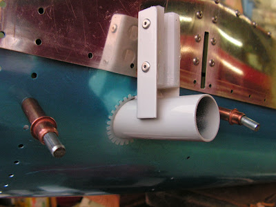
Step 1: Bolt the Brake Reservoir to the Firewall Upper using the hardware called out by Vans' Aircraft.

Builder's note: It's not called out but I am planning on fire caulking the gap around the bottom fitting that goes through the firewall.


Step 2: 
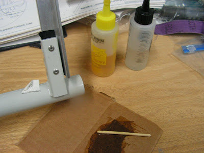
Secure the Reservoir Brake lines to the Brake Reservoir. Loosen the Nylon Nuts, insert the reservoir brake lines, push hard until they bottom-out in the Male Nylon Tee, then tighten the Nylon Nuts. Use thread sealant for the connection between the Male Tee and the brake reservoir.

Builder's note: I used Ez-Turn on the threads.


Step 3: Secure the Reservoir Brake lines and Cross-Over Brake lines (the four brake lines attached to the right side master cylinder) to the bottom of the Panel Base using the hardware called out on page 32-02 of the RV-12 plans.


This complete page 32-02.

Reference: page 32-03

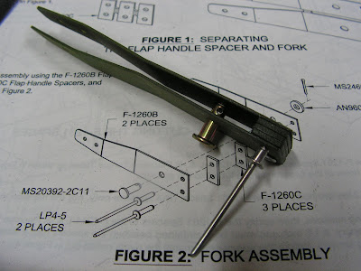
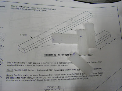
Step 1: Separate the Flaperon Mixer Bellcrank into individual parts.


Step 2: Rivet the Flange Bearing to the Flaperon Mixer Bellcranks.


Step 3: 
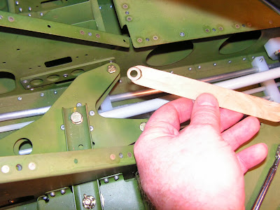
Make the Flap Handle/Pushrod Assembly using the parts called out on page 32-03 of the RV-12 aircraft plans. Thread in the rod-end bearing to attain the dimension given in the figure in the plans (note the dimension is from the centerline of the rod-end bearing to the edge of the Flap handle.)


This completes page 32-03.

Reference: page 32-04

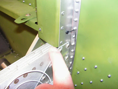
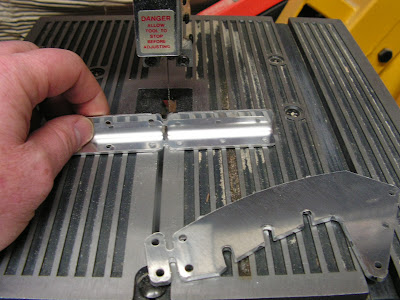
Step 1: Trim the corners from the two Flap Handle Blocks.
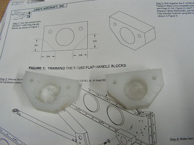


Step 2: Secure the Flap Handle/Pushrod Assembly to the inboard Seat Ribs using the Flap Handle Blocks and hardware called out by Vans Aircraft on page 32-04.

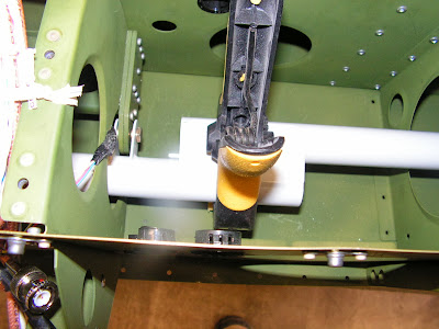
Builder's note: this is a good time to complete steps 1 & 2 on page 53-09 if installing the ADS_B system.. These two steps install a wire shield to protect the cable from rubbing on the flap handle.

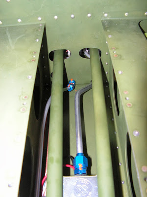
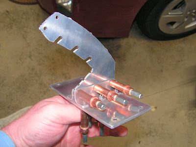
Step 1: page 53-09 Use a bench vice or hand seamer to bend up the Wire Routing Bracket F-00050 flanges as show in figure 1 on page 53-09 of the RV-12 aircraft plans.


Step 2: page 53-09 Secure the Flap Handle/Pushrod Assembly and Wire Routing Bracket to the inboard Seat Ribs as shown in Figure 2. Use the Flap Handle Blocks and the hardware called out.

Reference: page 32-04

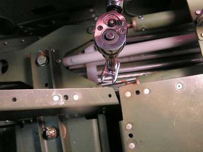
Step 3: Bolt together the Flaperon Mixer Arms Installed previously, see page 32-04, figure 2), the Flap Handle Pushrod using the hardware called out.


Step 4: 
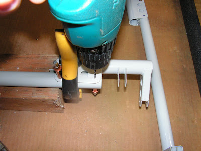
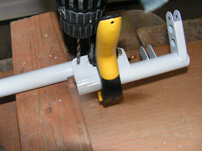
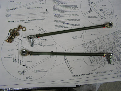
Make two Control Stick Pushrods according to the dimensions given using a # 3 drill and 1/4-28 tap (see page 32-04 of the RV-12 plans.)


This completes page 32-04.

Reference: page 32-05

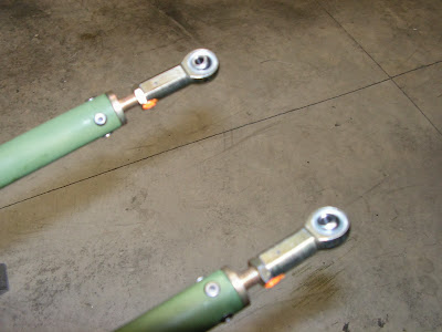
Step 1: Make two Control Stick Pushrod Assemblies.


Step 2: 
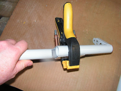
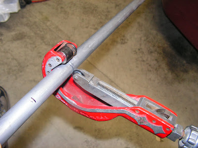
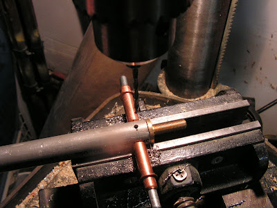
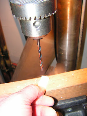
Clamp the Bushing BS Brass Bushing in a bench vise(be carful not to over tighten or gouge the bushing), then drill the inside diameter using a 1/4 bit.

Builder's note: I used a lathe at work to complete the above step.

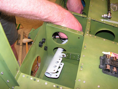
Step 3: Use a file to progressively remove material from the ends of both bushings until they closely fit between the flanges of the brackets on both ends of the Control Column.


Step 4: Use a file to progressively remove material from the ends of the tubes in the Control Sticks which sleeve the Brass Bushings. Remove material until, when bolted in place, the bracket on the Control Column clamp on the brass bushings and just clear the tubes.


Step 5: 
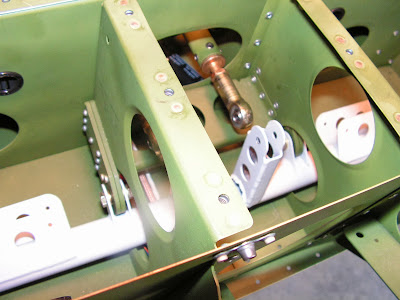
Attach the Control Sticks to the Control Column using the hardware called out in figure 2 on page 32-05.


Step 6: Attach the outboard ends of the Control Stick Pushrod Assemblies to the Control Sticks.


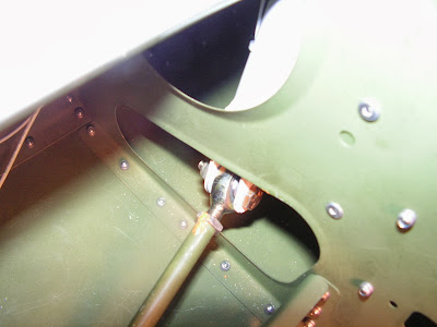
Builder's note: I used the "No Sweat" method called out in my video mentioned above.

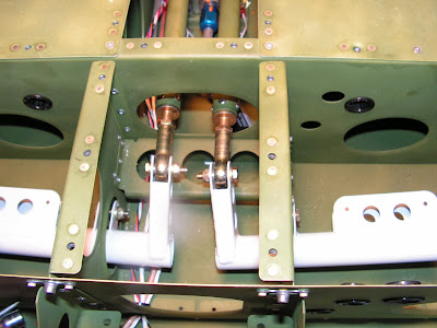
Step 7: Attach the inboard ends of the Control Stick Pushrod Assembilies to the Flaperon Mixer Bellcranks.


This completes page 32-05. I hope you enjoyed the video and it makes life a little easier.