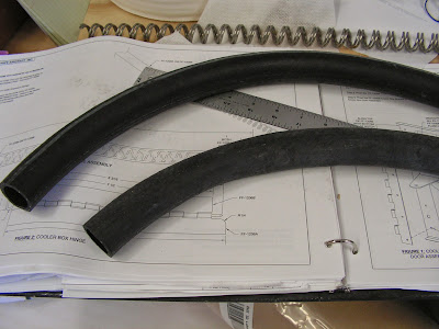
Today's entry is more work on the RV-12 airplanes cooling system. I called Van's Aircraft today because I couldn't find the hoses (H460) by name in the packing slips. As it turns out, it is the same as H173 3/16" fuel line.
Reference: 49-04
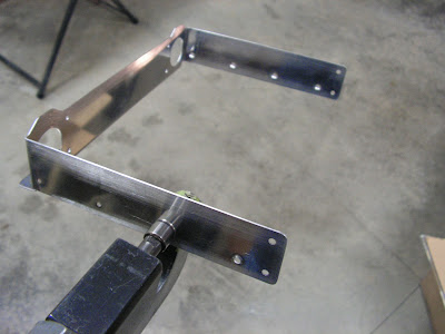
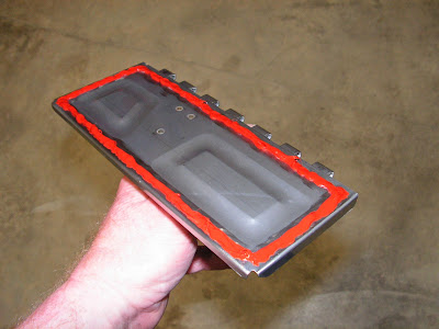
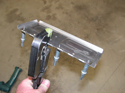
Step 4: Use the FF-1206C Hinge Pin to attach the Cooler Box Door Assembly to the FF-1206A Cooler Box Hinge. Safety wire the hinge pin to the FF-1204B Upper Cooler Box Rib. Use the provided safety wire holes in the upper cooler box rib.

This completes page 49-04.
Reference: 49-06
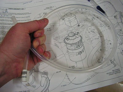
Step 4: Cut a 24 inch long piece of EA HOSE H460 to make the FF-1220 Overflow Bottle Hose.

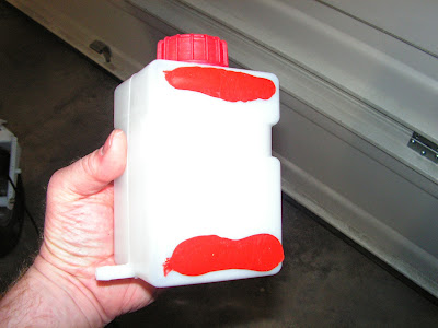
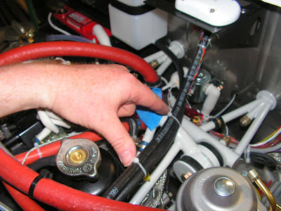
Step 9: Slip the FF-1220 Overflow Bottle Hose over the stem on the 922 327 Overflow Bottle.

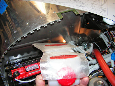
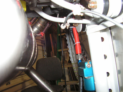
Step 10: Attach the 922 327 Overflow Bottle to the F-1201A Firewall Upper using the F-1201V Coolant Bottle Strap and hardware called out.

This completes page: 49-06
Reference: Page 49-07
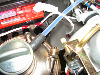
Step 1: Slide the free end of the F-1220 Overflow Bottle Hose over the barbed stem on the 922 665 Expansion Tank Assembly.

Step 2: Route the F-1220 Overflow Bottle Hose using tie-wraps.
Reference: Page 49-10
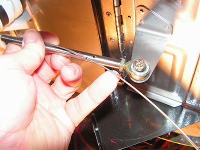
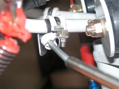
Step 5: Insert the bent end of the CT A-740 BLACK Push Pull Cable wire into the FF-1210 Cable End.

Step 6: Insert the cotter pin through the hole in the FF-1210 Cable End with the eyelet facing the side of the cable end (as shown in Figure 3 page 49-06). Rotate the cotter pin 90 degrees then bend the legs of the cotter pin around the cable end.
Step 7: Screw the jam nut onto the rod end as shown in Figure 3. Screw the rod end all the way into the FF-1210 Cable End until it bottoms out on the CT A-740 BLACK Push Pull Cable wire. Tighten the jam nut against the cable end.
Step 8: Using the hardware called out in Figure 3 attach the rod end to the FF-1205B Cooler Box Bracket.
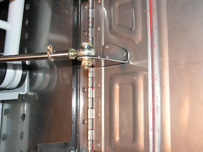
Step 9: Verify proper operation of the Cooler Box Door Assembly. If needed, loosen the clamps and reposition the CT A-740 BLACK Push Pull Cable so that the cooler box door assembly closes tightly leaving a 1/16 gap between the knob and the F-1201A-1 Instrument Panel. When satisfied safety wire the push pull cable to the cushioned clamp as shown in Figure 3 on page 49-06.
This completes page 49-10 and this entry.