Sunday, November 24, 2013

Vans Aircraft RV-12 Airplane Build, Section 34: Canopy Installation (part 2)

Reference: Page 34-02, 34-03; 2.5 hours

Today continues the work on the RV-12 aircraft canopy frame and the first (of many) installation of the canopy frame onto the airframe.

Step 4: Measure mark and drill the four side canopy angles. See the illustrations provided by Van's Aircraft on page 34-02 for dimensions.


This complete page 34-02.

Reference: RV-12 airplane plans page 34-03

Step 1: Attach the canopy frame and struts to the fuselage.


Step 2: Pace 1/8" cardboard spacers between the canopy frame and the fuselage canopy decks on the airframe.


Step 3: With the canopy frame closed check the edge clearences as called out by Van's aircraft and bend the frame as needed. Also make sure the frame doesn't catch on the insturment panel top.


My frame did required bending. Both for the last step and for the next entry, but more on that later.

Saturday, November 23, 2013

Vans Aircraft RV-12 Airplane Build, Section 34: Canopy Installation (part 1)

Reference: Page 34-02; 2.0 hours

Today starts a new section of building the RV12 airplane. I'm also changing the format of the blog and am going to paraphrasing each step verse recording them verbatim from the plans. The steps will still be numbered so you can match up the pictures with the steps in your plan.

Step 1: Drill both ends of the canopy gas struts. The plans were updated to version 3 on 6/8/12 and the hole sizes changed. One is now 1/4" and the other is 3/8". Yes I used a unibit and it worked well.


Step 2: Countersunk the two holes in the frame to fit a #10 screw. According to Van's Aircraft these should be either flush or can protrude up to 1/32".


Match drill the rivet holes int the canopy frame, deburr and install blind rivets as called out by Van's Aircraft on page 34-02 figure 2.


File and sand the weld on the center of the canopy's front bowonly where the canopy plastic will sit. There is a detail drawing in the plans on page 34-05 that will help.


Attach the gas struts top the canopy frame with the included hardware. Note the strut cylinders go towards the front of the airplane.

Next trim the gas strut attach screws (the ones that attach to the canopy frame) so that only 2 threads are sticking out past the end of the nuts.


Step 3: Position the Latch Handle Stop on the Canopy frame. The dimensions are given on page 34-02 figure 2 of the RV-12 airplane plans. Deburr and attach it using the rivets called out.


That's it for todays work and entry. So long until next time.

Thursday, November 21, 2013

Vans Aircraft RV-12 Airplane Build, Section 54: Stiffener Retrofit (part 3)

Reference: Page 54-06; 1.0 hours

Today is the last work to finish up the firewall stiffener on the RV12 airplane.

Step 1 & 2: Rivet the MOD stiffeners into place using the rivets called out by Van's Aircraft.

Builder's note: I riveted the original diagonal stiffeners F-1202N-R & -L back in at this time as well. Also don't forget to fill the four rivet holes on the upper firewall with rivets!


Step 3: Cover completely with fuel tank sealant the head of each newly installed rivet located on the forward side of the firewall.


Fill the unused hole in the skin by working fuel tank sealant into the groove between skin and stiffener. Give the sealant plenty of time to cure before using a razor blade to trim ir flush to the outer skin surface.


Builder's note; Be sure to check for any holes in the firewall sealant in the corner where the new stiffeners go. These will need to be fill if any exist.

Step 4: Reinstall the gascolator and radiator hoe clamp with hose. If fitted.


Well that's it for the firewall stiffener mod on the RV 12 airplane.

Monday, November 18, 2013

Vans Aircraft RV-12 Airplane Build, Section 54: Stiffener Retrofit (part 2)

Reference: Pages 54-03, 54-05, 54-06; 4.0 hours

This entry is a continuation of the installation of a firewall stiffener mod produced by Vans Aircraft for the RV-12 ELSA airplane.

Step 2: Cleco the lower end of the Stiffener Assembly to the Firewall Bottom at the #30 hole drilled out eariler.

Rotate the Stiffener Assembly into the upper corner of the firewall bottom until the upper-most corner of the assembly is about coincident with the tangent of the firewall radius. Spacers should not contact the firewall stiffening deads.


Step 3: Match-drill #30 the Firewall at the upper-most hole called out. Insert a celco into this hole.


Match-drill #30 the firewall bottom using the remaining #30 holes in the Stiffener Assembly as a guide. For best results begin near the midpoint and insert clecos along the way. Remove the Stiffener Assembly and deburr the holes in the firewall.


Step 4: Rivet the Stiffener Assembly to the Firewall using rivets called out, place the manufactured heads on the firewalls' fwd side.


Step 5: NA Install landing gear bolt removed previously.

This completes page 54-03.

Reference: page 54-05

Step 1: Slide a piece of thin steel between the Fuselage Side Skin and the Fwd Skin Stiffenr then cut off the stiffener to the dimension shown on page 54-04 figure 1 of the RV12 airplane plans. Use A cutting wheel in a die grinder.

Builder's note: I tried this step as written and then just drilled out the remaining rivets holding the stiffener. Removed the part from the fuselage and trimmed it as required. It was much easier than standing on my head leaning over the edge of the fuselage.


Step 2: Cleco the MOD-R & -L Skin Stiffener to the bottom surface of the Firewall Shelf using the twp #30 drilled out rivet holes.

Builder's note: I used the aluminum angle sharppened on one end to shave some of the firwall sealant out of the corner, being careful not the scratch the fuselage skins or firewall.


Drill four #30 holes through both shelf and stiffener from above at the four new hole locations marked earlier.

Remove the angle, clean out any chips or burrs and cleco at all six hole locations.


Step 3: Match-drill #30 the Fuselage side skin using the MOD Skin Stiffener holes as guides. Make sure the aft end of the angle is properly positioned using the dimension then drill the aft-most hole first. Insert clecos along the way.


This completes page 54-05.

Reference page 54-06.

Step 1: Lay out rivet locations at the fwd end of the 1295 MOD Skin Stiffeners by drawing a line on the outside of the Fuselage Side Skin using thee row of rivet holes drilled in the previous step.

Mark off the hole locations using the spacing called out on page 54-06 of the RV12 planes. Final-drill #30 through both skin and MOD Skin Stiffener at the new hole locations, inserting clecos along the way. Disassemble and deburr.


That's it for todays work.

Sunday, November 17, 2013

Vans Aircraft RV-12 Airplane Build, Section 54: Stiffener Retrofit (part 1)

Reference: Pages 54-02, 54-03, 54-04; 4.0 hours

Today is the beginning of the rest of your RV airplane project! Van's Aircraft has introduced a new retrofit kit that helps reinforce the firewall and keep the forward fuselage panels from oil canning. I first read about it on Vansairforce.com which is an active Vans Aircraft forum. I am going creating a new index Label called RV12 Updates. So let's get started.

One last thing, I did jump around a little in this section while waiting for primer to dry. Now let's get to it!

NOTE: Use Boelube or equivalent when drilling through stainless steel firewall.

Steps 1-4 are NA: My RV12 is still in construction and these steps deal with a completed and flying RV12.

Step 5: Remove the four screws attaching the gascolator bowl to the gascolator and remove the bowl.


Builder's note: I had to loosen the screw I am pointing at, in the picture below, to get the left back retainer screw holding the gascolator bowl in place.


Step 6: NA I have not installed the landing gear so there was no need to remove the attachment screw.

Step 7: Remove the called out rivet. See figure 3 on page 54-02.


This completes page 54-02.

Reference: 54-03 Step 1: Cleco the FF-1204E Firewall Stiffener Spacer to the FF-1204D Firewall Stiffener noting orientation. See figure 1 on page 54-03. Match-Drill #40 the stiffener using the #40 holes in the spacer as guides then remove the clecos. Machine countersink the #40 holes in the spacer on the side facing the firewall for the head of the called out rivet. Separate the spacers by removing the shaded area shown in figure 1 detail and deburr.

Rivet the spacers to the stiffener using a rivet squeezer and the rivets called out. Hereafter refer to this unit as the Stiffener Assembly.


Reference page 54-03

Step 1: Separate the Skin Stiffener into F-1295-MOD-L & R and deburr.

Builder's note: For the next steps I did both the left and right side of the fuselage at the same time.

Step 2: Remove the three upper-most rivets attaching the F-1202N Fwd Skin Stiffener to the F-1270-R & -L.

Builder's note: After messing with this process I ended up removing the stiffeners from the airplane, cutting them and re-riveting them back in. More on that in the next blog post.


Step 3: Remove the two rivets attaching the tab of the F-1202N-R & -L Fwd Skin Stiffeners to the aft side of the Firewall Upper.


Remove the two called out rivets on the F-1201B Firewall Shelf.


Draw a centerline between the two now empty holes on the shelf and layout four new holes locations using the spacing shown in the plans but do not drill them yet.


This completes page 54-04 and this entry. Next time I will go back and pick up the few steps I jumped over and then proceed.

Saturday, November 16, 2013

Vans Aircraft RV-12 Airplane Build, Section 31A: Wing Electrical Interconnector Update (part 2)

Reference: Pages 31A-09; 1.5 hours

This entry will complete the fuselage side of the Wing electrical interconnectors for the RV-12 airplane.

Step 1: Position the F-00033 Wing Electrical Template on the F-1226-L Seat Ramp Florr.

Match drill #30 the four holes into the seat ramp floor. Position the wing electrical template on the right side of the aircraft then match-drill the right side seat ramp.

Remove the template and final-drill #19 all eight holes.


Step 2: Tap 8-32 the four holes in both the F-00034-L and -R Wing Electrical Brackets.


Step 3: Tie-wrap and secure all wires.


Step 4: Install the Floating 8 Pos Connector Female to the F-00034-L Wing Electrical Bracket.

Install the ES-00078 Floating Connector Male to the F00034-R Wind Electrical Bracket.


Step 5: Install the Wing Electrical Brackets to the Seat Ramps using the mounting screws.


That completes this entry. There is still a finishing plate that goes over the wing electrical plug that will be installed later. So I am done messing with wiring for now and next time will go into installing the Firewall Stiffener Retrofit kit for the RV-12 aircraft.

Friday, November 15, 2013

Vans Aircraft RV-12 Airplane Build, Section 31A: Wing Electrical Interconnector Update (part 1)

Reference: Pages 31A-07, 31A-08; 2.75 hours

Vans Aircraft has updated the wing to fuselage electrical interconnect for the RV12 airplane. I touched on it in the other entry for today. You will noticed I started in the middle of the section this is because my wing for the RV12 are in storage, so I will need to plan the update for the wings at another time.

Also I am including a head scratcher on the Builder's Gotcha list. One of the wires has been changed to a new part number but the drawings in the plans don't reference it. The new wire is WH-L458 and is discussed later in this entry in more detail. The drawings in question are on page 42D-23 and 31A-07.


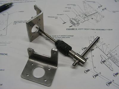
Step 1: NA as they were not installed Remove the F-1270B ASSMY from the left and right Side Skins.

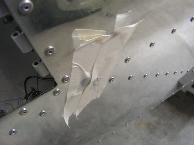
Step 2: Label all the wires for the wing connections.


Builder's note: I used heat shrink tubing and marked it with a Sharpie before shrinking it.

Steps 3, 4, & 5 Builder's note these steps didn't apply as this was new construction on the RV12 airplane.

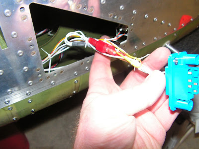
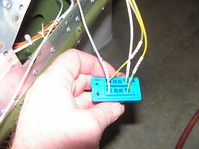
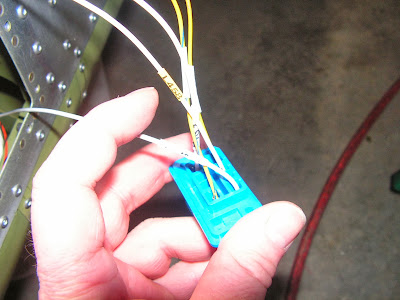
Step 6: Crimp an ES-00079 Floating Connector Pin 16-20 AWG on all the wires in Step 5. This is the WH-F57 (BRN/YEL) Stall Warn Wire, WH-L73(YEL), WH-L88(YEL/BLU), and WH-B183 (WHT) Wing Ground Wires. See figure 2 & 3 on page 31A-07 of the RV12 aircraft plans.


Step 7: Insert the pin on the WH-B183(WHT) Wing Ground Wire into position 1 on the back of the Floating 8 Pos Connector Female.


Step 8: Insert the pin on the WH-F57 (BRN/YEL) Stall Warn Wire into position 2 on the back of the ES-00077 Floating 8 Pos Connector Female.


Step 9: Insert the pin on the WH-L88(YEL/BLU) into position 4 on the back of the ES-00078 Floating 8 Pos Connector Male.


Step 10: Insert the pin on the WH-B183(WHT) Wing Ground Wire into position 1 on the back of the ES-00078 Floating 8 Pos Connector Male.


Step 11: Insert the pin on the WH-L73(YEL) into position 5 on the back of the ES-00078 Floating 8 Pos Connector Make.


This completes page 31A-07.

Reference page 31A-08

Steps 1 - 6 D180 Builder's note: As I am not installing a Dynon D180 These steps do not apply to my Rv12 airplane.

Step 6: (SV-D1000) EFIS: Insert the pin on the WH-274 (WHT) Lighting Power Update Wire into position 8 on the back of the ES-00077 Floating Connector Female.


Step 7: Was complected previously. Cut the spade terminal off the WH-B184(WHT) and strip the wire. Crimp on a pin to the WH-B184(WHT) Nav/Strobe Power Wire.


Step 8: 
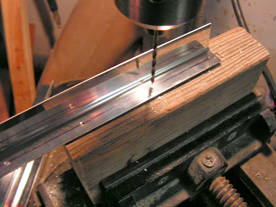
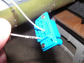
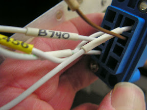
Fabricate the WH-B740(WHT) Strobe Sych Wire by Cutting a 57 inch long piece of 18 AGW wire. Strip the ends of the wire and install an ES-00079 Floating Connector Pin on each end.


Step 9: Insert the pin on one end of the WH-B740(WHT) wire into position 7 on the back of the EF-00077 Floating 8 Pos Connector Female.

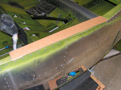
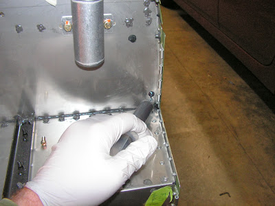
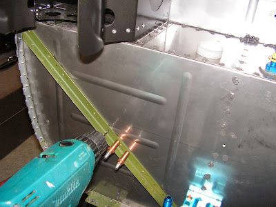
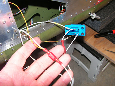
Route the WH-B740 (WHT) wire across the fuselage following the same routing as the WH-B184(WHT) wire.

Insert the pin on the free end of the WH-B740 (WHT) wire into position 7 on the back of the ES-00078 Floating Connector Make.


Builder's note: Here is the Gotcha. Page 42D-23 in the plans Step 3 talks about wire number L458 being inserted into position 6. However the drawings all show the old wire number B268 on both sides of the fuselage as being inserted into position 6. No big deal just leave you wondering for a while!


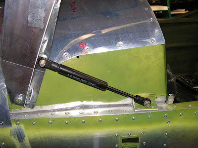
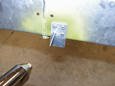
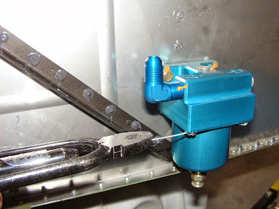
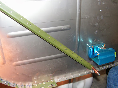
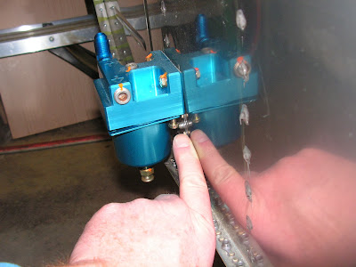
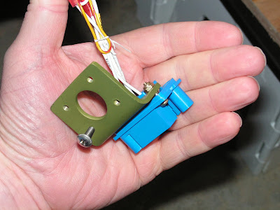
Builder's note: Also there is no mention in the direction to ground the Noise Filter other than as a note on a drawing on page 31A-08. So I went ahead and ground it to the seat frame as pictured below.