Wednesday, March 30, 2011

RV-12 Tailcone (Part 9)

Reference: page 10-09; 1 hour

Step 1: Remove the area shown hatched to separate the F-1238-L & -R Snap Bushing Brackets as shown.


NOTE: Step 2 through 6 explain installation for the F-1279-L Upper Left Skin and F-1238-L Snap Bushing Bracket. Installation for the F-1279-R Upper Right Skin and F-1238-R Snap Bushing is a mirror of the left and should be done at the same time.

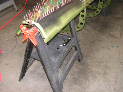
Step 2: Hook the F-1279-L Upper Left Skin J-Stiffener into the cutouts in the F-1208, F-1209 and F-1210 Frames. Cleco the upper left skin to the frames and F-1280-L Left Side Skin as shown.


Step 3: Cleco the F-1238-L Snap Bushing Bracket to the F-1279-L Upper Left Skin.


Step 4: Match-Drill #30 the holes called ou in the F-1279-L Upper Left Skin J-stiffener into the F-1238-L Snap bushing Bracket. Cleco the first hole before drilling the next. Then remove, deburr, re-cleco. A 12 inch ectended bit may be helpful.


Builders note: After this I prepared the parts for painting and primed them.

Tuesday, March 29, 2011

RV-12 Tailcone (Part 8)

Reference: page 10-8; 1 hour

Another short day of working on the RV-12 aircraft. One thing on the static system is to make sure the tee on the left side is not below the static port on that side. Otherwise water can get in the system. Had this happen on our Mooney and it was an expensive fix!

Step 6: Follow the 'Installing the Static Air System instructions to install the left and right side static sources into the F-1280-L & -R Left and Right Side Skins in the locations called out.

Step 7: Install the end of the 1/8 ID clear Plastic Tube over the right static source. Route the 1/8 ID Clear Plastic Tube along the inside flange of the F-1208 frame. Follow the inside flange of the F-1208 Frame to the left side. Secure the tube with plastic tie wraps through the holes along the flange. Install the loose end of the 1/8 ID Clear Plastic tube to the plastic tee. Position the plastic tee at the same height as the J-stiffener located directly above the static source. Install the end of a separate piece of 1/8/ ID Clear Plastic Tube to the left static source and the other end of that tube to the plastic tee.


Step 8: Install a 1/4 inch long piece of 1/8 ID Clear Plastic Tube to the remaining leg of the plastic tee. Builder's note: I found it easier to install this before installing the other section of 1/8 tube. Connect one end of the PT 1/4 OD Polypropylene tube to that same leg of the plastic tee. Route the polypropylene tube down the inboard flange of the frame, then to the J-stiffener of the F-1281-L Lower Left Skin as shown in plans. Route the tube inside the J-stiffener 'hook' of the lower skin with the WH-P30 shown on page 10-08. Coil the remainder of the tube and secure the coil to the inside of the lower left skin with tape or string.


This completes page 10-08.

Monday, March 28, 2011

RV-12 Tailcone (Part 7)

Reference: page 10-8; 1 hour

Didn't get much work done on the RV12 today. But an experimental aircraft is like eating an elephant, just keep taking on bite at a time.

Step 4: Route a string from the forward end of the existing structure, through the center of each frame, to the F-1211 Assembly. The string will go out though one of the stabilator control calbe sutouts and back in through the other stabilator control cable cutout as shown in plans. Return the end of the string to the forward end of the existing structure. Tape both ends of the string to the inside surface of the bottom skin.


Step 5: Route the WH-P30 Trim Wires. Start six inches aft of the F-1211 Assembly, route the trim wires through the snap bushing. Route the trim wires inside the J-Stiffeners 'hook' of the F-1281-L Lower left skin to the forward edge of the existing structure. At the holes provided in the J-stiffener aft of the F-1208 Fuse Frame secure the trim wires using plastic wraps. Coil the remainder of the trim wires and secure the coil to the inside of the lower left skin with tape.

Saturday, March 26, 2011

RV-12 Tailcone (Part 6)

Reference: page 10-06, page 10-07, page 10-8; 6.5 hours

Well the RV-12 is starting to really grow in size! As the end of section 10 of Van's Aircrafts plans draws near, I'm leaning towards attaching the tail feathers to the tailcone rather than jumping over the next section.

Reference: page 10-06

Step 3: Rivet the F-1284-L & -R Shear Clips to the F-1283A & B J-Stiffeners using rivets called out in the plans.
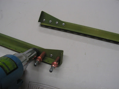


Step 4: Cleco the F-1283A & B J-Stiffeners to the F-1282-L & -R Bottom Left and Right Skins.

Step 5: Match-Drill #30 the holes in each of the F-1282-L & -R Bottom Left and Right Skins into the F-1283A & B J-Stiffeners.

Remove, clear away chips, deburr and re-cleco.


Step 6: Rivet the F-1283A & B J-Stiffeners only to the J-stiffener of the F-1282-L & -R Bottom Left and Right Skins using rivets called out in plans.
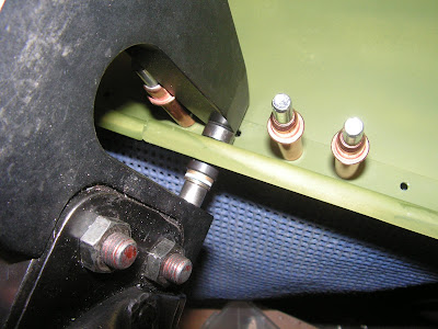


Step 7: Place the F-1282-L bottom Left Skin upside down across two sawhorses that are at least 38 inches tall. Locate the forward sawhorse just forward of where the F-1208 Frame will be, and the rear sawhorse just aft of where the F-1210 Frame will be.

Builder's note: I used 31-32" tall saw horses with no problems.

Step 8: Hook the J-Stiffener cutout of the F-1208, F-1209 and F-1210 Frames onto the J-Stiffener of the F1282-L Bottom Left Skin. Cleco each fuse frame to the left bottom skin.


Step 9: Hook the J-Stiffener of the F-1282-R Bottom Skin into the J=Stiffener cutout of the F-1208, F-1209, and F-1210 Frames. If the J-stiffeners interfere with J-stiffener cutouts in the fuse frames, either the J-stiffeners can be bent or the cutouts in the frames can be enlarged slightly until the J-stiffeners clear. Cleco the bottom right skin to the F-1282-L. Bottom Left Skin and frames.


This completes page 10-06.

Reference: page 10-07

Step 1: Hook the J-Stiffeners of the F-1281-L & -R Skins into the cutouts in the F-1208, F-1209, F-1210 Frames. Cleco the lower skins to the frames and F-1282-L & -R bottom Left and Right skins. Capture the F-1283A & B J-Stiffeners with the bottom and lower left and right skins.
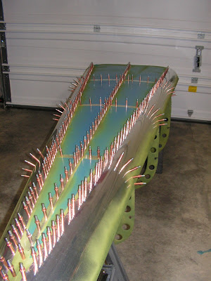


Step 2: Place masking tape over all of the holes that are within seven inches of the forward edge of each tailcone skin. Those will be left open for the remainder of this section.
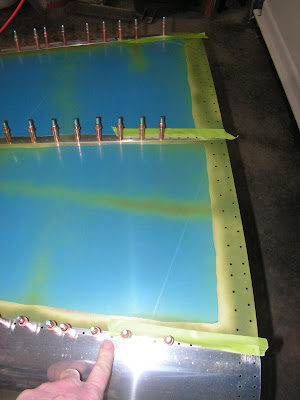


Step 3: Rivet the F-1282-L & -R Bottom Left and Right Skins together. Rivet the F-1208, F-1209 and F-1210 Frames to the bottom left and right skins. Rivet the F1281-L & -R Lower Left and Right Skins only to the bottom left and right skins, and the F-1283A & B J-Stiffeners using rivets called out. Leave open all remaining holes in thelower left and right skins.


This completes page 10-07.

Reference page 10-08:

Step 1: Turn the assembly over so the frames are pointing up. Support the assembly with two sawhorses, one at the F-1208 Frame and one at the F-1210 Frame.


Step 2: Cleco the F-1211 Assembly to the aft end of the existing structure.


That's it for today we will pick up here next time.

Friday, March 25, 2011

RV-12 Tailcone (Part 5)

Reference: page 10-02, page 10-06 ; 6.5 hours

As I discussed earlier now that I am getting ready to work on the RV12's tailcone skins, it is now time to get the skins ready.

Page 10-02

Step 1: Identify the tailcone skins. The F-127 8op Skin does not have a J-Stiffener formed on either of the long sides. The F-1282-L Bottom Left Skin has J-stiffener formed on both of the long edges, while the F-1282-R Bottom Right Skin has only one. The remaining tailcone skins have a J-stiffener formed on one edge, and each left skin is mirrored by the right.

Step2: Prepare the skins shown in Figure 1 for a lap joint by deburring and breaking (Section 5K) the edges. The edges to be lap joints are called out in figure 1 on page 10-02. Both edges of the F-1278 Top skin must break in the same direction. The remaining skins must break in the same direction as the J-stiffener. Begin with the F-1282-R Bottom right skin, since it is least likely to be seen. When breaking the edges of the F-1278 Top Skin gradually increase the break angle towards the aft end.


This completes page 10-02

Reference page 10-06

Place the F-1282-L & -R bottom Left and Right Skins on a flat surface.

Step2: Trim the called out material from the F-1282-L Bottom Left Skin as shown.


After completing these steps time was spent prepping and priming the skins for the next steps.

Wednesday, March 23, 2011

Picking Up the RV-12 Airframe Kits

Wednesday's weather was the best all week and the remaining RV-12 airframe kits are ready at Vans Aircraft. So Ethan and I headed up to Vans to pick up the RV-12. With some planning, 2X4 stickers and plenty of tie down straps, the RV-12 airframe (minus the tail kit) plus the finishing kit fits nicely in the back of a Toyota Tacoma. We strapped the kits together into one unit and then secured the entire load to the truck. I wouldn't drive cross country like this, but we don't live far from Vans Aircraft so this method worked well. Below is a picture, at home, with some of the straps already removed.

Tuesday, March 22, 2011

RV-12 Tailcone (Part 4)

Reference: page 10-04; 3.5 hours

The RV-12 rear tail-cone bulkhead will be finished today. It will then be trial fitted to the stabilator.

Step 7: Cleco the F-1211G Tail Skid Bracket and the F-1211D Attach Brackets (with bushing flange on the outboard side) to the F-1211A Fuselage Bulkhead and F-1211B Bulkhead Doubler.


Step 8: Rivet the F-1211A Fuselage Bulkhead to the F-1211B Bulkhead Doubler, using the rivets indicated.


Builder's note: For the two low rivets i removed the tail skin bracket to prevent it from interfering with the die, however a small diameter female die would work.


Reference Page 10-06

Step 1: With the Stabilator Assembly on a workbench, check the fit of the F-1211 Assembly hinges with the Stabilator Assembly hinge brackets. Determine the best symmetric choice of wishers to minimize lateral play and prevent binding throughout the stabilator travel. While determining the hinge hardware, use one washer between the bolt head and bracket, and use only one washer on each side of the bearing. The called out AN960-416 Washers may be substituted with AN960-416L washers as necessary.


Step 2: Temporarily super glue the washers, determined in Step 1, to the outboard side of the HS-1213A Inboard Hinge Bracket, and the inboard side of the HS-1213B Outboard Hinge Bracket. Be sparing with the super glue, contact only the washer and hinge bracket. Apply a minimal amount of oil to the bolt shank, then locate the washers using the bolt called out.

Builder's note: I ran into a GOTCHA as the AN4_12A shank would not fit through the Hinge Bracket holes. I went back to see if I had missed the step of drilling them, however it is not called out in the plan. So I final-drilled them to 1/4 inch. This required a short bit and an angle head drill. And a soft touch as I didn't want to damage the nutplate. The hole were then deburred.


Step 9: Rivet the F-1211D Attach Brackets and F-1211G tail Skid Brackets to the F-1211 Assembly using the rivets indicated.

Hereafter refer to the F1211-A and the F1211B Bulkhead Doubler as the F-1211 Assembly.


Step 10: Rivet the nutplates to the F12-11 Assembly as shown in the plans using the indicated hardware.


Step 11: Cleco the F-1211C-L 7 -R Hinge Brackets and the VA-146 Flange Bearings to the 1211 Assembly.


Step 12: final-Drill #30 the holes common to the F-1211C-L & -R Hinge Brackets, the VA-146 Flange Bearings, and the F-1211 Assembly. Cleco each hole before drilling the next. Disassemble, deburr the re-cleco in place.

The picture below doesn't show each hole celcoed as instructed. It was staged as I disassembled the part.


Step 13: Rivet the F-1211C-L & -R Hinge Brackets and the VA-146 Flange Bearings to the F-1211 Assembly.


Step 14: Insert the snap bushing into the F-1211 Assembly.

Monday, March 21, 2011

RV-12 Tailcone (Part 3)

Reference: page 10-04; 3.5 hours

Today starts the work on the rear fuselage bulkhead for the RV-12 tailcone. The RV-12 is a experimental light sport airplane (E-LSA) kit offered by Vans Aircraft.

Step 1: Rivet the F-1211D Attach Brackets together. Deburr the 1/4 in. holes per call-out on page 10-04 Figure 1. Install the bushing (oversize press fit) as shown. If necessary use a C-clamp with a small socket opposite the bushing.


Step2: Flute the F-1211A Fuselage Bulkhead as called out (four places) enough to reduce the slight pucker in the flange. Cracking may result from excessive force.

Builder's note: The picture below shows the left one completed and the right side before fluting.


Step 3: Cleco the F-1211B Bulkhead Doubler to the F-1211A Fuselage Bulkhead as shown.

Step 4: Cleco the F-1211G Tail Skid Bracket to the F-1211A Fuselage as shown in plans. Clamp the tail skid bracket in place.


Step 5: Match-drill #30 the holes of the F-1211B Bulkhead Doubler into the F-1211G Tail Skid Bracket and deburr the holes.

Builder's note "I also match drilled to #30 the solid rivet holes between the Bulkhead and Bracket Doubler. Then deburred these as well. Just a force of habit from building the RV-10.


Step 6: Final-Drill #12 the 3/16 holes called out. Disassemble, deburr, clear away chips, and re-cleco in place.


After completing the last step I prepped and primed the part for assembly. These will be assemblied after the zinc chromate dries. Until next time!

Sunday, March 20, 2011

RV-12 Tailcone (Part 2)

Reference: page 10-03; 3.5 hours

Well, it finally feel like I'm starting to get some traction on the RV-12 airplane. Still debating whether to attach the empennage (Section 11) when the tailcone is complete or to move on to the wings. This is the process I followed during construction of the RV-10 and it worked well. There is still time before the desition must be made.

Step 1: Fabricate the F-1211G Tail Skid Bracket from the AEX Tie Down extrusion using the F-1211G-DT Drill template as shown in plans.


Step 2: Remove the tabs from the F-1211B Bulkhead Boubler and beduree the bends called out.

Builder's note: I am not sure why the plans say to deburr the bends but not the rest of the part. It may because of it being a critical area for cracks. I went ahead and deburred all of the edges.


Step 3: Machine countersink the holes in the F-1211B Bulkhead Doubler.


Step 4: Seperate the F-1211D Attach Brackets by removing the material called out in the plans. Deburr.

Builder's note: Don't deburr the holes at this time! These are deburred a very specific way in a later step.


Step 5: Mark, then separate the F-1284-L & -R Shear Clips.


Step 6: Mark, then separate the F-1211C-L & _R Hinge Brackets.


Step 7: Mark the F-1283 J-Stiffener with the part numbers called out in the plans. Remove the area shown hatched in the plans to separate the F-1283A, B, & C J-Stiffeners.


This completes page 10-03.