Tuesday, July 30, 2013

Vans Aircraft RV-12 Airplane Build, Section 31: Fuselage wiring (part 8)

Reference: Pages 31-10, 31-11; 3.0 hours

I am coming to an end of how much of the RV-12 aircraft wiring I can do without having the tail cone in place. My main focus is now to get the flight controls finished and the wings fitted before finish the installation of the tail cone. You may recall my wings are stored at a secondary location, so while I can easily move the fuselage front section around this is the time to do these projects.

Step 1: Install the ES AS212 12 Volt Power Outlet and the audio jack on the WH-RV12-Music harness to the F-1230A Bulkhead.


Step 2: Make the WH-B54(WHT) Power Outlet Ground by cutting a piece of 18 gauge wire 8 inches long. Strip both ends. Install a ring terminal on one end and a female spade connector on the other per the call-outs in Figure 1. Install the spade connector to the negative terminal on the back of the Power Outlet.


Reference: page 31-11

Step 1: Purchase a set of 7/8 handle bar grips from a local bike shop. Remove the plug from the end and install the grips over the end of the WD-1212 Control Sticks.

Builder's Note: I found a nice pair of foam grips at the local Bike-N-Hike store.


Step 2: Drill 1/4 inch a hole in the center of the handle bar grip plug. Remove the nut from the switch on each Push to Talk Harness switches and screw into the plug from the bottom. Screw the nut back onto the switch.

Builder's Note: In drilling the plugs I did need to drill the backside of the plugs to 3/8 inch with a unibit. Also I put a drop of thread lock on the nut to prevent them from loosening up.


Step 3: Starting at the top of the WD-1212 Control Sticks thread the Push to Talk Harnesses through and out the bottom of the control sticks. Loop wires up and tie wrap them to the shank and the bottom of tie gooseneck on the control sticks.

Builder's Note: I found using a small weight (i used a washer) and light test fishing leader was easier to work through the control stick and then this could be used to pull the wires through the control sticks.


Step 4: Temporarily install the Control Sticks by sliding a bushing into the stick and then a bolt to attach the stick to the WD-1210 Control Column. See Page 32-05 for more detail.


Step 5: Route the Push to Talk Harnesses through the snap bushing in the F-1215 Seat Ribs just inboard of the WD-1212 Control Sticks.

Step 6: Strip the end of each WH-F83(BLK) PTT Ground wire in the Push to Talk Harnesses. Crimp on a ring terminal called out in figure 1 (on page 31-11).


Step 7: On the left side of the aircraft use the hardware called out in figure 1 to attach the ring terminal on the WH-F83(BLK) and the ring terminal on the WH-B183(WHT) to the most inboard Seat Rib (remove any primer or paint that would prevent the terminal from grounding.


Builder's Note: I also use a conductive paste that prevents corrosion from setting in at a later time.


Step 8: On the right side of the aircraft use the hardware called out in figure 1 to attach the ring terminal on WH-F83(BLK), WH-B183(WHT) and WH-B54(WHT) to the most inboard Seat Rib (remove any primer or paint that would prevent the terminal from grounding.


Step 9: Route the remaining WH-F66 (WHT)PTT Transmit Wire from the Co-Pilot Push To Talk Harness and WH-F67 (WHT) PTT Transit Wire from the Pilot Push To Talk Harness forward through the snap bushing in the F-1203A and F-1202F Bulkheads, fuel flow cushioned clamp, up the back side of the firewall and over the rudder pedals, up through the Panel Base, through the lower snap bushing in the Left Inst Stack Support and through the cushioned clamp near the left ES CPU FAN. These wires will be added to the Tunnel harness later.


Builder's Note: The RV-12 plans called out the above wires as white and Blue but on my harness they are only white.

This completes page 31-11. Next time I will delve deeper into the flight control installation.

Monday, July 29, 2013

Vans Aircraft RV-12 Airplane Build, Section 31: Fuselage wiring (part 7)

Reference: 31-09, 31A-07 ,31A-08; 1.5 hours

Today is more fun, with the wiring on the RV-12 aircraft kitted by Van's Aircraft. There is a GOTHCA (of sorts) in steps 5, 8 & 11 on page 31-09. The spade connectors mentioned in these steps have been replaced with new connectors refer to on page 31A-08

Step 5: Route the WH-184(WHT) Nav/Strobe Power Wire through all the Seat Ribs to the right side of the aircraft and crimp on a connector (See page 31A-08 for the new connector design). Secure the connector on the new wing wiring assembly on the right side of the aircraft. Adjust the wire so that there is an equal amount of slack on each end.


Step 6: Separate from the WH-RV12-OPTIONAL harness the group of seven twisted wires, strip the ends, then route them through the snap bushings in all but the most outboard Seat Rib on the left side of the aircraft. Route the seven twisted wires through the rectangular opening in the second to mot outboard seat rib on the left side of the aircraft as shown in figure 1 on page 31-09.


Step 7: Find the supplied WIRE AUTOPILOT SERVO seven stranded wire in the kit and trim to 85 inches to create the WH-B170 Autopilot Harness. Strip the wires on one end.

Step 8: Matching colors, crimp together in paris the same connectors BUILDER'S NOTE: Refer to page 31A-08 for new connectors! I used the old one and then had to cut them off. YEL, BLU, WHT and BLK wires from the seven twisted wires in the WH-RV12-OPTIONAL harness and seven twisted wires in WH-B170 Autopilot Harness.

Matching colors, crimp together in pairs in the same connectors the remaining RED, ORG and WHT/BLK wires from the seven twisted wires in the WH-RV12_OPTIONAL harness and the seven twisted wires in WH-B170 Autopilot Harness.


Route the WH-B170 Auto Harness back through the rectangular hole, through the snap bushings in the Seat Ribs to the center of the aircraft. Add a Plastic Tie 4.5 inch in the hole just forward of the rectangular opening (see figure 1 page 31-09) going around the wires and back through the same hole into itself.


Step 9: Create and label two WH-B183 (WHT) Wing Ground Wires from 18 gauge wire. Strip one end of each and attach an updated connector from page 31A-07. Each will be attached to the new wing wiring connector. in section 31A. Route the wires inboard through the snap bushings in the Seat Ribs. Strip the routed end of the wire and crimp on a ring terminal per the callouts in figure 1 on page 31-09. This ring terninal will be attached to the inboard most seat rib later.


Builder's Note: One nice way to label wires is use white shrink tube and a fine Sharpie marker. Write the number on the tube and then shrink it to the wire.


Step 10: Lay the WH-RV12-OAT harness and WH-B170 Autopilot Harness into the System Blocks. Route both through the Center Section Assembly, through the cushoined clamp attached to the fuel pump and the snap bushings in the F1206A and F-1207B Bulkheads.


Step 11: Strip the ends of the seven WH-B170 Autopilot Harness wires. Crimp on connectors. Builder's note: Use page 31A-08 as a guide to the new molex connector to be used. Don't use the spade connectors and then cut them off as I did!


This completes page 31-09 and this entry of the build on the RV-12 until next time.

Sunday, July 28, 2013

Vans Aircraft RV-12 Airplane Build, Section 31: Fuselage wiring (part 6)

Reference: pages 31-08, 31-09, 31A-08; 3.0 hours

This is a continuation of the wiring for the RV-12 aircraft I'm building. Again there are a number of changes because of updating to the Dynon SkyView. For example all of the spade connectors for the autopilot servos will be installed and then replaced with new molex connectors.

Step 1: Using the callouts in figure 2 on page 31-08 of the RV-12 airplane plans, drill #30 a pilot hole for the outside air temperature probe. Use a unibit to final-drill this hole to 3/8.


Step 2: Install the WH-RV12-OAT harness in the hole created in Step 1. Route the wires back through the snap bushing in the Seat Ribs to the center of the aircraft.


This completes page 31-08.

Reference: page 31-09

Step 1: Route the WH-RV12-OPTIONAL harness over the rudder pedals, through the fuel flow cushioned clamp and through the snap bushings in the F-1202F and F-1203A Bulkheads.


Step 2: From the WH-RV12-OPTIONAL harness separate out and route the WH-L72(YEL/RED) wire through the snap bushings in the Seat Ribs on the left side of the aircraft. Separate out the WH-L73(YEL) and WH-L88(YEL/BLU) wires and route them through the snap bushings in the seat ribs on the right side of the aircraft.


Step 3: Make and label the WH-B184(WHT) Nav/Strobe Power Wire by cutting 53 inches of 18 gauge wire and striping each end.

Step 4: ON the left side of the aircraft crimp both the WH-B184(WHT) and WH-L72(YEL/RED) wires together in the same female spade connector.


Builder's note: This spade connector is used in the new updates but the old F-1270B Assy will be replaced. See page 31A-08 for the updated assembly.


That completes this entry on the wiring for the RV-12 airplane. The best advice I have when it comes to wiring is go slow, focus on each step you are doing and document, document document!

Saturday, July 27, 2013

Vans Aircraft RV-12 Airplane Build, Section 31: Fuselage wiring (part 5)

Reference: pages 31-06, 31-07, 42D-02, 42D-27 (rev 3); 5.0 hours

If you are following this blog for the RV-12 airplane you will notice I am jumping between sections. Last entry was dealing with wing attachment pins and todays with fuselage wiring. One way to sort out of this out is to use the index of pages off to the right on this page. That way it is easy to look up all the entires dealing with a single page.

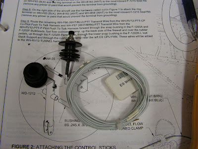
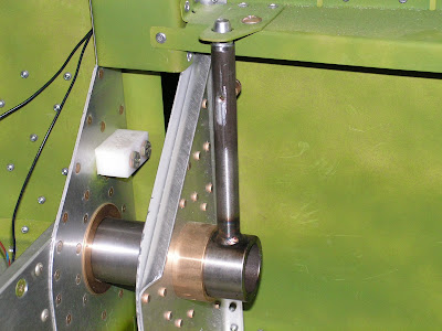
Step 1: Install snap bushings in the F-1204C-L & -R Fwd Bulkhead Sides and F-1204B-L & -R Aft Bulkhead Sides.


Step 2: 
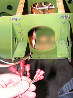
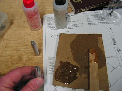
Choose one of the two ES RS 49-496 Reed Switches. Trim one of the two wires back to 4.5 inches in length. Strip the ends of both wires coming from each switch. To the 4.5 inch long wire crimp on a ring terminal.


Step 3: 
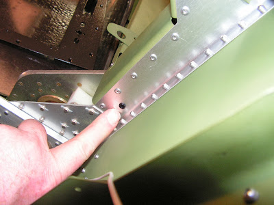
Using the hardware called out in figure 2 & 3 (on page 31-06) attach the ES RS 49-496 Reed Switches to the Arm Rests (attach the ring terminal from Step 2 at the same time). Align the inboard end of the switch with the inboard face of the armrest. Route the remaining wire on the right side of the aircraft and both wires on the left side of the aircraft through the snap bushings installed in Step 1. Crimp on butt splices to the switch wires.


Step 4: 
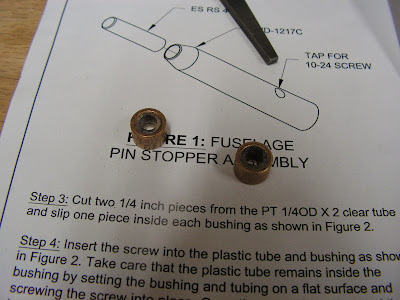
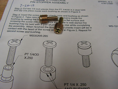
To test the Reed Switches, temporarily connect a multimeter as shown by Van's Aircraft in figure 5 on page 31-06 by connecting one wire coming from the left reed switch to the positive multimeter lead and the remaining reed switch wire and negative multimeter lead to the fuselage frame (ground). Turn the multimeter to the continuity check mode. Snap the left Fuselage Pin Stopper into the Fuselage Pin Latch. The multimeter should indicate continuity. Repeat this step for the right reed switch.

When the stoppers are not latched there should be no continuity through the reed switch. If the stoppers are engaged and there is continuity, try moving the reed switches in or out. Be sure to check that if the stopper is not in the pin latch hole but under the pin latch there still should be no continuity. The only position that should create continuity is when the stopper is fully engaged in the pin latch holes!

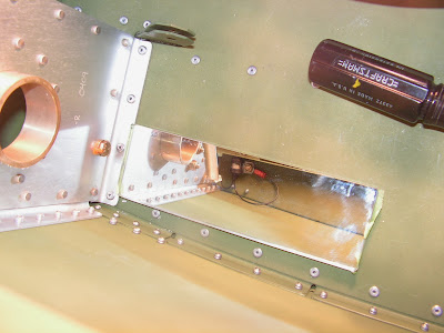
It may be necessary to trim the WD-1217 tube. When installed, the top of the tube should be approximately centered on the reed switch. Remove the stopper from the fuselage pin and trim 1/32 of an inch from the top of the tube. Reassemble the fuselage pin with the stopper and test. Repeat as required. Do not remove more than 1/8 of an inch.

Builder's note: I ended up removing material from the left hand pin assemble and part of the rubber on the cushioned clamp to get it to work, while the right side worked the first time.


Step 5: 
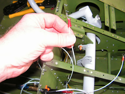
Make WH-B167 (WHT) Spar Pin Interconnect Wire by cutting a 42 inch long piece of 22 gauge wire and striping both ends. Crimp one end to the butt splice installed in Step 3 on the right Reed Switch, route through the Wire Run Conduit and crimp the other end to one of the butt splices installed in Step 3 on the left reed switch. Crimp the remaining butt splice on the left switch to the WH-F50 (BRN/BLU) Spar Pin Wire.


Step 6: Double check that hardware installed in Step 3 is tight if altered when troubleshooting in Step 4.

This completes page 31-06.

Reference 31-07

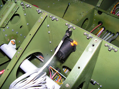
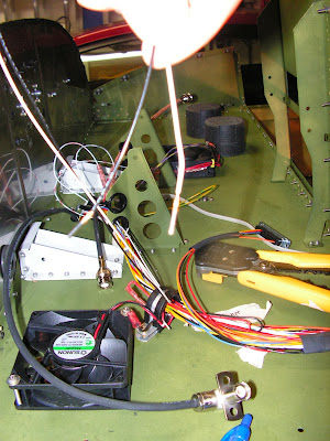
Step 1: Route the wires of the WH-RV12-OPTIONAL harness (those coming out of the main 25-pin d-sub compactor but not attached to the AP-74 25-pin d-sub compactor) through the cushion clamp near the left ES CPU FAN and lower snap bushing in the Inst Stack Support. Separate the approximately 22 inch long WH-L80(YEL/PRP) and WH-L82 (YEL/GRN) wires from the harness.


Step 2: Route the remaining WH-RV12-OPTIONAL harness through either of the snap bushings in the forward center region of the Panel Base leaving 31.5 inches (BUILDER'S NOTE: This length will be changed with the update of the SkyView in a later blog entry) to the main d-sub above the panel base. Tape the optional harness down so that this distance does not change as you route wires.

Step 3: If installing the optional autopilot, use a unbid to enlarge the hole for the auto disconnect switch to 1/2 inch diameter in the F-1202A Instrument Panel for the button in the WH-RV12-APDC Autopilot Disconnect. Install the autopilot disconnect as shown in figure 1 of the RV-12 aircraft plans on page 31-07.


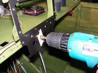
BUILDER'S NOTE: The disconnect switch has been updated to include a molex connector in the wiring. See page 42D-02 and 42D-27. Most of page 42D-02 does not apply to my airplane because I had not installed the Dynon DEK 180 previously.

Reference: 42D-02, Step 26: Label then cut the wires coming from the WH-RV12-APDC Autopilot Disconnect six inches behind the Instrument Panel. Remove the autopilot disconnect and set aside for later.


Reference: 42D-27

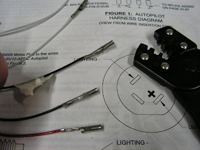
Step 1: Find the wire previously cut in page 42D-02, Step 26 for the WH-RV12-APDC Autopilot Disconnect that are still attached to the fuselage. Crimp ES-00006 Molex Socket to the end of each of autopilot disconnect wires. Insert each wire into a ES-00007 Molex Receptacle as shown in figure 1 on page 42D-27 of the RV-12 airplane planes.


Step 2: Crimp ES-00005 Molex Pins to the wires coming from the Autopilot Disconnect switch.


Step 3:Enlarge hole to 1/2 inch in Instrument panel.Builder's Note: This was done previously. There are some repeated steps from section to section.


This completes page 42D-27

Back to Reference: page 31-07

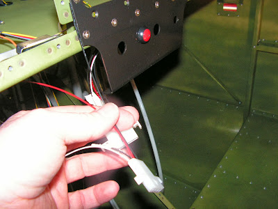
Step 4: Route all the wires coming from the back of the WH-RV12-APDC Autopilot Disconnect up through one of the two snap bushings in the Panel Base. Crimp together into the same side of a butt splice the red wire coming from the autopilot disconnect WH-F177(RED) and the WH-L80 (YEL/PRP).


Step 5: Make a WH-B179(WHT) Cockpit Light Power Wire and WH-B180(WHT) Cockpit Light Ground Wire by cutting two pieces of 22 gauge wire 153 inches long.

BUILDER'S NOTE: This is the method I used, however there is an alternative way of wiring the light in section 42D.

Step 6: Crimp the WH-B179(WHT) Cockpit Light Power Wire into the open end of the butt splice with the WH-L80(YEL/PRP) and WH-F177 (RED) wires crimped in the other end.

Step 7: Crimp the WH-B180(WHT) Cockpit Light Ground Wire into the open end of the butt splice with the WH-L82(YEL/GRN) and WH-F178(BLK) wires crimped in the other end.


Step 8: Route the WH-B179(WHT) Cockpit Light Power Wire and WH-B180(WHT) Cockpit Light Ground Wire along the route of the Wh-Q54(ORN/BRN) Fuel Level Wire. Cover the ends of the wires to prevent them from shorting out to the aircraft structure then coil the extra wire for later use. See page 31-05.


Step 9: Route the longer WH-F78(WHT) and WH-F79(BLK) wires coming from the back of the WH-RV12-APDC Autopilot Disconnect back through the lower snap bushing in the Ins Stack and cushion clamp near the lest ES CPU FAN.


Step 10: 
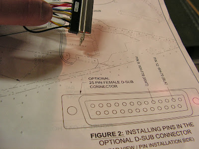
Remove the d-sub backshell from the main 25-pin d-sub connector on the WH-RV12-OPTIONAL harness. Insert the pins on the ends of both WH-F78(WHT) and WH-F79(WHT) wires through the heat shrink and into the correct pin locations as shown in figure 2 on page 31-07 in the 25-pin d-sub female connector. Check with a gentle tug that each wire has snapped into place. Slide the heat shrink supplied with the optional harness up the wires until its length is centered about the exit of the backshell then activate the heat shrink.

Builder's note: I did not shrink the heat drink tubing as directed above. There are still wired that will need to be added and subtracted because of the Dynon SkyView update.


This completes page 31-07. There is a lot to digest and a lot of jumping around because of the updates. Most of this will become an academic discussion as the newer wiring harness are provide by Van's Aircraft. But for those who got caught in the middle of the updates this is reality!

Friday, July 26, 2013

Vans Aircraft RV-12 Airplane Build, Section 30: Wing Attachment (part 1)

Reference: pages 30-02; 1.0 hours

These next few sections for the construction of the RV-12 aircraft are proving interesting to document. Because of the installation of the Dynon Skyview three different wiring section are all interconnected. Also there are a number of new options and revisions. Not to mention having assemblies of the airplane stored at two different locations. So we will see how this all turns out!

Step 1: Tap the hole in each of the Fuselage Pin Stoppers as shown in figure 1 on page 30-02 of the RV-12 plans.


Step 2: Insert the Magnet all the way to the bottom of the hole in the Fuselage Pin Stopper then fill the remainder of the hole with epoxy and allow it to set. Repeat for the second magnet and fuselage pin stopper.


Step 3: Cut two 1/4 inch pieces from the PT 1/4OD clear tube and slip one piece inside each bushing.


Step 4: Insert the screw into the plastic tube and bushing. Take care that the plastic tube remains inside the bushing by setting it on a flat surface and screwing the screw into place. Once the screw is well stared the bushing may be held with pliers or a vise. When finished the bushing and plastic insert will be in contact with the head of the screw. Repeat on the second screw.


Builder's note: I painted the fuselage pins before completing to the next step.

Step 5: Install the Spring and Fuselage Pin Stopper into the Fuselage Pin. Apply a small amount of Loctite #242 to the screw threads and insert the screw. When properly installed the fuselage pin stopper can be moved up and down by applying pressure to the screw on the side of the fuselage pin assembly.


Repeat the process for the second fuselage pin, but insert the screw on the opposite side of the fuselage pin assembly.

With these pins built it is time to move the fuselage front section to the warehouse where the wings are stored for fitting.