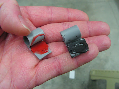
Welcome back to my RV-12 airplane blog. I'm starting on page 49-15 which deals with installing the Cowl duct seals. The plans call for using silicone sealant to glue them on. So I used Silicone II (after proper cleaning) and the peeled right off the next day! So I made two test pieces one with fuel seal the other with RTV as can be seen below. The fuel seal peeled a part easily. The RTV took alot of abuse before failing, so I am using RTV sealant to glue the seals on.

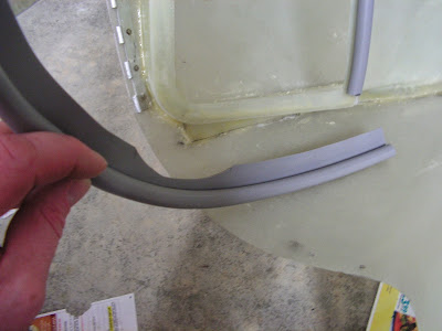
Step 3: Clean COWL 12 DUCT SEAL A, B & C with denatured alcohol.

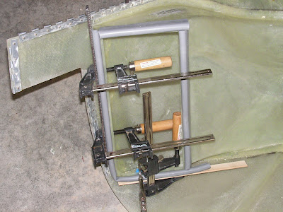
Step 4: Bond the seals to the COWL DUCT INTERFACE using silicone (use scrap aluminum and clamps on the curved area).
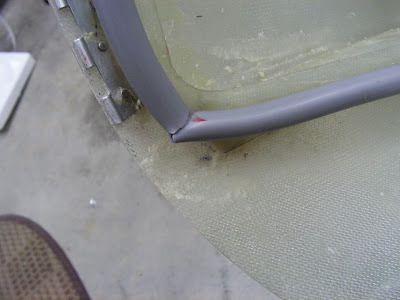
Step 5: After the silicone is dry, use a razor blade to slit the lower outboard portion of the COWL DUCT SEAL C to allow the seal to compress without bunching up.

This completes page 49-15. Post script: The RTV stuck really well.
Reference: page 49-21
Builder's note: The newest set of section 49 doesn't show a page 49-21. The one I have is rev 1 dated 6/26/14. It deals with installing the blast cooling tube for the rectifier. So here it goes.
Step 6: Using blind rivets attach the cooling shroud to the Rectifier.
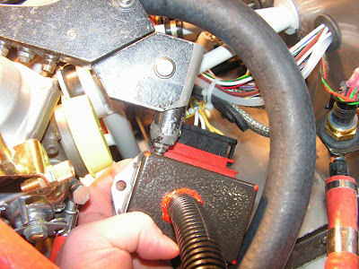
Step 7: Reattach the Rectifier to the Firewall Shelf.
Step 8: Cut the Duct NT 5/8 to 24 inches long. to make the blast tube.

Step 9: Squeeze the blast tube slightly, then insert the end into the Cooling Shroud.

Step 10: Tie wrap the Blast Tube to the Radiator Hose to prevent the blast tube from chafing on other components.

Step 11: Add a bead of RTV around the end of the blast tube where it enters the Cooling shroud.

This completes page 49-21.
Reference: 50-02
Step 1 (Older Style Center Panel): NA I used the new panel.
Step 2: Route the Throttle Cable through the left hole in the center panel, through the nut and washer and the cable penetration grommet in the F-1201A Firewall Upper. Feed the cable slack to the forward side of the firewall upper until the throttle cable is seated in the panel.
Step 3: Route the Choke Cable through the remaining hole in the center panel, through the nut and washer and the cable penetration grommet in the F-1201A Firewall Upper. Feed the cable slack to the forward side of the firewall upper until the choke cable is seated in the panel.


This completes this entry and page 50-02 for the RV-12 airplane.

