Today I will continue on the the Pitot tube and spinner assembly for the RV-12 airplane.
Step 6: Insert the locking screw to "tap the #36 hole in the Pitot Block. Remove the screw and insert the Pitot Tube through the prop shaft and into the pitot block. Turn the pitot tube until the marks on the pitot tube and the block align. Insert the locking screw and tighten by hand until it just bottoms on the pitot tube. Check the front of the tube for proper orientation. The head of the locking screw will not be in contact with the pitot block.
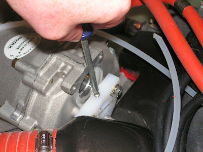
Step 7: Route the Pitot Line to the pitot tube. Cut a one inch piece of .062X3/8 104-0375062 TUBE to make the Pitot interconnect and slip in over the end of the pitot line and Pitot tube. The pitot line and pitot tube should butt against each other.
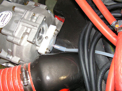
Step 8: Double wrap safety wire around the Pitot Interconnect.

This completes page 47-02.
Reference Page 47-03.
Before starting this page read the documentation for propeller installation included with the prop and engine.
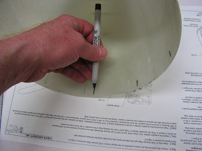
Step 1: Copy the lines marked around the perimeter of the Spinner onto the inside of the spinner with a fine point pen. Trim and sand the lower portion of the spinner to the scribe line.
Step 2: Carefully remove the area on the sides of the Spinner for the propeller cutouts. Start by drilling holes with a step drill about 1/116 inch inside the radius at the top of the cutout area. Use a fine tooth saw to cut slits up to the curved portion of each tracing. Save the lower portion of the removed section in make the Gap Fillers later.


Step 3: Sand the tip of the Spinner until the outer diameter matches the outer diameter of the Pitot Bushing. Make sure it remain parallel to the back of the spinner. Using sand paper, create a small radius on th inside edge of the spinner opening to allow the bushing to mate properly with the spinner.

Step 4: Roughen the surface of the Bushing with a course sand paper where it contacts the spinner. Apply blue Loctite to the bushing and insert in to the spinner.
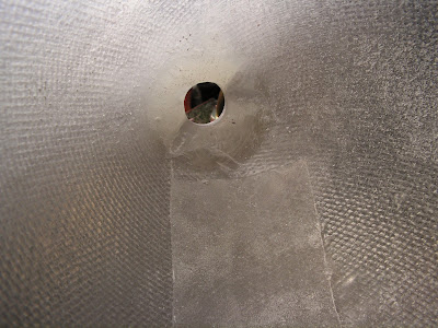
Builder's note: My spinner had cracks in the epoxy near the tip on the inside. As can be seen below. So I used a Dremel to remove the cracked material.

Step 5: Using a fine point pen draw a screw centerline on the flange of the Spinner Plate.

Step 6: Attach the Spinner Plate, Hub Mount Half to the prop shaft usign the hardware provided with the prop.
Step 7: Attach the propeller blades, Hub Clamp Half, and Front Spinner Bulkhead with the remaining hardware and Spacers. Pitch the propeller blades to "high pitch" (with the leading edge of the prop in the most forward position.)

Step 8: Tape around the base of the prop blades to prevent scratching the blades. Slide the spinner over the assembly with the pitot tube extending through the spinner bushing. Seat the spinner firmly and clamp the spinner to the spinner plate.

This completes page 47-03.
Reference: Page 47-04
Step 1: Attach a striaght edge to astand to the corner of the ruller is centered at the center of the pitot tube.

Step 2: Remove the lower spark plugs from each cylinder to allow the propeller to turn easily.
Step 3: The pitot tube should remain within 1/16 of an inch from the corner of the ruler as the propellor turns through its entire rotation. Adjust the Spinner and repeat the process until it is within that tolerance.
This completes page 47-04.
Reference: Page 47-05
Step 1: Using a #30 bit match drill the pilot holes for the four screws in the Front Spinner Bulkhead. Cleco after drilling each hole.

Step 2: Locate the screw holes in the Spinner and Spinner back plate. These should intersect the line on the flange and the lines marked previously on the spinner. Drill #30 and cleco as you go. To prevent pillowing of the spinner between screws, start drill midway between the prop blades and work out towards the blade cutouts in the spinner.

Step 3: Trim any overhang of the Spinner beyond the spinner backplate with a sanding block.

This completes this entry in the RV-12 airplane build.

