Today's entry deals with the fitting of the cooling duct inside the RV-12 cowl. Step 1: Trim the COWL 12 COOLING DUCT with snips to within 1/16 of the scribe lines. Trim away the area inside the scribe line for the oil cooler opening on the cooling duct. Sand the remaining material away to the scribe lines.

Step 2: Align the oil cooler opening in the COWL 12 COOLING DUCT with the opening/fin area on the Oil Cooler Box Assembly, then clamp the two together at the bottom flange of the Oil Cooler Box Assembly.

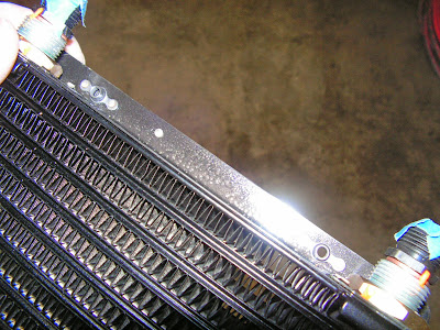
Step 3: Match-Drill #12 the two attach holes in the top flange of the Oil Cooler Box Assembly into the COWL 12 COOLING DUCT.

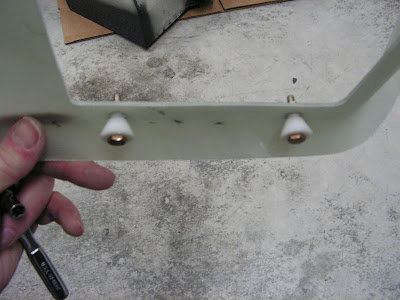
Step 4: Unclamp the Oil Cooler Box Assembly from the COWL 12 COOLING DUCT then install nutplates onto the top flange of the Oil Cooler Box Assembly as shown in Figure 2 on page 49-12.
Step 5: Attach the Oil Cooler Box Assembly to the COWL 12 COOLING DUCT using the hardware called out.

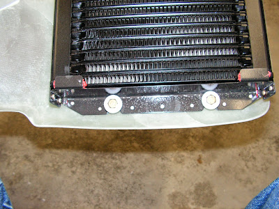
Step 6: Press the COWL 12 GUIDE tightly into the top of each slot in the bottom edge of the Oil Cooler Box Assembly as shown in Figure 2 and match-drill #12 the hole in the guide into the COWL 12 COOLING DUCT.

Step 7: Attach the COWL 12 GUIDE to the COWL 12 COOLING DUCT using the hardware called out by Van's Aircraft.
Step 8: Remove the Oil Cooler Box Assembly.
This complete page 49-12 of the RV-12 airplane plans.
Reference: Page 49-13
Step 1: Except for the edge noted in Figure 1 trim the COWL 12 DUCT INTERFACE with snips to within 1/16 of the scribe lines then sand the remaining material away to the scribe lines.

Step 2: Remove the left hinge pin attaching the COWL 12 BOTTOM to the fuselage. This will allow the cowling to be flexed enough to insert the COWL 12 COOLING DUCT into position. Re-install the hinge pin.

Step 3: Align the front of the COWL 12 COOLING DUCT with the oval shaped air inlet on the front of the COWL 12 BOTTOM per the detail view in Figure 2, View A-A. This may require trimming the aft edge of the cooling duct to the forward face of the EA RV-12 RADIATOR.

Step 4: Using the dimension in Figure 2, View C-C clamp the the COWL 12 COOLING DUCT to the COWL 12 BOTTOM.

Step 5: Drill #40 and cleco the top flange of the COWL 12 COOLING DUCT to the COWL 12 BOTTOM every 6 to 8 inches. Do not worry about abandoning a mis-drilled hole and re-drilling if you decide to reposition the cooling duct slightly since the holes will be filled when finishing the lower cowl later.
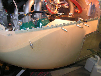
Step 6: Look with a mirror through the COWL 12 BOTTOM air exit to ensure that the bottom of the COWL 12 COOLING DUCT is parallel to the bottom of the EA RV-12 RADIATOR. Drill #40 a single hole in the bottom flange of the cooling duct near the aft edge.


Step 7: Remove the COWL 12 BOTTOM and check the fit of the top and bottom edges of the COWL 12 DUCT INTERFACE on the aft edge of the COWL 12 COOLING DUCT. If not satisfied with the fit of the interface repeat Step 6 to change the position of the cooling duct's bottom flange. When satisfied drill #40 and cleco the bottom flange of the duct interface to the cowl bottom every 6 to 8 inches. Re-install the cowl bottom.
Step 8: Mark the COWL 12 COOLING DUCT 5/16 of an inch away from the FF-1209 Seal Face. Remove the COWL 12 BOTTOM and cooling duct and trim away material aft of the marked line to make room for the COWL 12 DUCT INTERFACE.


Step 9: Slide the COWL 12 DUCT INTERFACE over the aft trimmed edge of the COWL 12 COOLING DUCT. Material may need to be removed from the outboard flange of the duct interface abutting the COWL 12 BOTTOM. When satisfied with the fit of the duct interface to the cooling duct, reinstall the cowl bottom with the interface in place. See Figure 2.

Step 10: Use 1/4 inch thick spacers to evenly space the top and sides of the COWL 12 DUCT INTERFACE off of the FF-1209 Seal Face (the COWL 12 COOLING DUCT may need to be trimmed further). See Figure 2, View B-B. Drill #40 and cleco the duct interface to the top and side of the COWL 12 COOLING DUCT in several locations. Remove the COWL 12 BOTTOM and continue drilling #40 the lower and bottom sides that were inaccessible with the cowl bottom installed.

Step 11: Mark the edges of the COWL 12 COOLING DUCT on the COWL 12 BOTTOM.


Step 12: Remove the clecos holding the COWL 12 DUCT INTERFACE, COWL 12 BOTTOM and COWL 12 COOLING DUCT together.
Step 13: Use 100 grit sand paper to sand the entire bonding areas between the COWL 12 DUCT INTERFACE, COWL 12 BOTTOM and COWL 12 COOLING DUCT. Also sand the areas where layups will be made, see Page 49-12.

This completes this day's work on the RV-12 airplane. The last step on this page will be completed after the duct is fiberglassed into place. Until later.

