Today's entry contines the work on the cooling system for the RV-12 E-LSA airplane. Step 3: Install the free end of the FF-1208B Radiator Hose - Output onto the 922 665 Expansion Tank Assembly using clamps as shown in Figure 1 on page 49-07.
Builder's note: Try as I may the spring in the upper hose was too long and need to be shortened to fit into the upper hose.


Step 4: Install the free end of the FF-1208A Radiator Hose - Input onto the 922 218 Water Inlet Elbow using clamps as shown in Figure 1.
This completes page 49-07.
Reference: page 49-11
Step 5: Rivet the FF-1212 Oil Cooler Frame to the FF-1215 Oil Cooler Spacers.
Step 6: Rivet the FF-1212 Oil Cooler Frame to the FF-1214 Oil Cooler Faceplate (do not rivet the nutplate attach holes at this time).
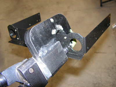
Step 7: Add a line of RTV to the inside of the Oil Cooler Box Assembly as shown in Figure 1. Slide the 886 034 Oil Cooler into the Oil Cooler Box Assembly.

Step 8: Use the 242 871 Hex Nuts called out in Figure 2 to attach the 886 034 Oil Cooler to the Oil Cooler Box Assembly.

Step 9: Screw the 956 641 Adapters into the top of the 886 034 Oil Cooler with 230 387 Gasket Rings and Loctite as shown in Figure 2.
Step 10: Plug the 956 641 Adapters on the 886 034 Oil Cooler to prevent construction debris from entering the cooler.

Step 11: Add RTV underneath the FF-1213 Oil Cooler Frame Bottom tabs as shown in Figure 2.
Step 12: Rivet the FF-1213 Oil Cooler Frame Bottom to the FF-1214 Oil Cooler Faceplate and the FF-1212 Oil Cooler Frame using the rivets called out in Figure 2.

Step 13: Deburr the edges of both slots along the bottom edge of the Oil Cooler Box Assembly.
The deburring was done prior to painting. This completes page 49-11 and this entry for the RV-12 airplane.

