Today's entry will soon be outdated, as my RV-12 airplane came with the old style e wing interconnect. This old style is being updated on my airplane and will of course be standard equipment. Just bare with me through the process.
Reference: Page 31A-02
Step 2: Remove the three screws on the W-Terminal Bracket on both wings.

Step 3: Make sure all the wires are labeled.

Step 4: Cut the ring terminals connected the the Terminal Blocks.

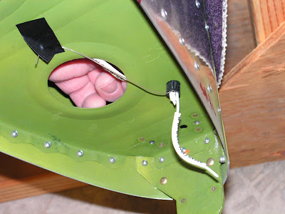
Step 5: Push the cut wires modified in step 4 through the snap bushings in the first nose rib.
Step 6: Set aside the two Terminal Ground Wires for later.
Step 7: Remove the snap bushings from the Nose Ribs and insert a snap bushing into the Wing Electrical Template.

Step 8: Tape three washers together that say "Tape Here" in the figure 3 drawing on page 31A-02.
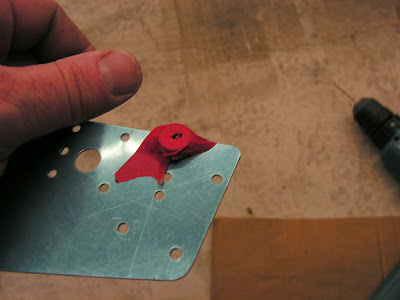
Step 9: Screw the Wing Electrical Template to the Nose Rib. Make sure the template is flush to the nose rib stiffening bead and parallel to the web of the nose rib.
Step 10: Match-drill #30 the hole that says "drill here First" in figure 3 on page 31A-02 of the RV-12 airplane plans.

After match drill that hole, slide washers behind the template and cleco match-drill #30 the remaining active holes show in figure 4.

Step 11: Remove the snap bushing and wing electrical template from the nose rib. Repeat the drilling on the other wing.
This completes page 31A-02.
Reference: Page 31A-03
Step 1: Reinstall the snap bushing ino the Nose Rib on each wing.
Step 2: Cleco and rivet a Doubler Plate to the Nose Rib on both wings.

Step 3: Attach the Standoffs to the inboard most NOse Rib on each wing.

This completes page 31A-03.
Reference: Page 31A-04
Step 1: Pull the wires back through the snap bushing in the Nose Rib.

Step 2: Strip the wires pulled back through the snap bushing and crimp on an ES-00079 Floating Connector Pin 16-20 AWG.
Step 3: Strip the cut end of the two terminal Ground Wires and crimp on a pin.

Reference: Page 40-07
Step 1: Trim the W-1222-L & -R Extensions back to within 1/16 of the scribe lines defining the part perimeter with a hand shear, then sand the extensions back to the scribe line.

Step 2: Fit the W-1222-L & -R Extensions to each wing tip then drill #30 the forward two and aft two holes into the upper flange and the W-1204E-L & -R Fwd Wing Tip Ribs. Remove the extensions and clear any drill chips then cleco back in place. Drill #30 all the hole locations into the lower flange and into the W-1204D Wing Tip Close-Out. Match-Drill #30 the three holes already in the wingtip (a bright light may help in revealing the hole locations underneath the fiberglass).


Step 3: Cover each wing tip in the area around where the flox on the W-1222-L & -R Extensions will touch with a release agent such as car wax. See Figure 1 and Figure 2. Add a glob of modeling clay or wax to the area where a nut will be placed (see Figure 1 and Figure 2).
Builder's note: I used packing tape and mold release with good results.


Step 4:NA as my wings are in a stand. Turn both wings upside down.
Step 5: Prepare approximately 2-3 fluid oz. of flox/epoxy resin mixture. Mix in flox until the concoction is just thick enough to not pour from the cup.
Step 6: Fill cavities in the upper flange of the W-1222-L & -R Extensions that abut the W-1204E-L & -R Fwd Wing Tip Ribs with flox/epoxy resin mixture, then cleco the extensions to the F-1204D Wing Tip Close-Outs. Immediately clean any flox/epoxy resin mixture that may have squeezed out.


Step 7: When the flox has set up, drill #30 the top center two holes into the W-1204E-L & -R Fwd Wing Tip Ribs.

Step 8: Remove the W-1222-L & -R Extensions from each wing tip. Sand away any of the flox that may have squeezed out around the perimeter of the part. Remove the modeling clay plug.

This completes page 40-07 and this entry into the RV-12 aircraft builder's log.

