There are a lot of little details in installing the engine controls on the RV-12 airplane. There have also been a few changes in the plans as noted below.
Step 1: Make two F-00001 Cable Spacers, one for each cushioned clamp called out in Figure 1. Note there are two different sized cushioned clamps. Cut remnant EA HOSE H151 from Section 49 the length of a cushioned clamp. Remove part of the circumference as shown in the plans so the cable spacer will be just long enough to wrap around the inside of the cushioned clamp.

Step 2: Orient the handle of the Choke Cable so that the longer of the two cables is on the right side, and the handle is vertical when locked. Secure the choke cable to the center panel by installing the nut and washer.
Step 3: Capture the Choke Cable with the cushioned clamp and corresponding F-00001 Cable Spacer. Install the cushioned clamp to the F-1202B Panel Base.

Step 4: Orient the handle of the Throttle Cable so that the longer of the two cables is on the right side. Secure the throttle cable to the center panel by installing the nut and washer.
Step 5: Capture the Throttle Cable with the cushioned clamp and corresponding F-00001 Cable Spacer. Install the cushioned clamp to the F-1202B Panel Base.

This completes page 50-03.
Reference: Page 50-04
NOTE: Guide the throttle cables above each of the choke cables. Guide the longer cable of the throttle and choke cables to the right.
Step 1: Capture the Throttle and Choke Cables with the cushioned clamp.
Step 2: Loosely attach the cushioned clamp with the four cables to the WD-1221 Engine Mount Standoff using another cushioned clamp and the hardware called out in Figure 1 on page 50-04. Orient the clamps so that the throttle and choke cables will not contact the WD-1220 Engine Mount Ring as shown in Figure 1, then tighten.
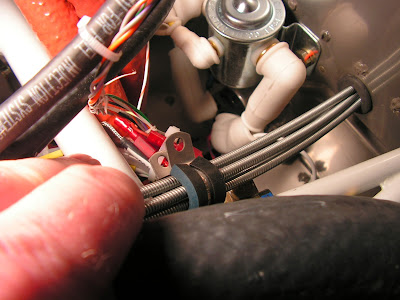
Builder's note: The plans call for a nyloc nut on the control cables on the forward side of the firewall. I have always heard this is a no no. So I used a metal loc nut as pictured.

This completes page 50-04.
Reference page 50-05
Builder's note: the First two steps on this page deal with replacing the return springs on the carburetors. The original springs will work but are stiff. To date the replacement springs have been defective and there is a service bulletin out on them. So I'm going to wait and see what Van's Aircraft comes up with before trying to replace the original Rotax springs.
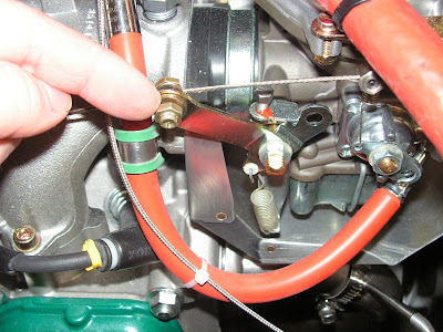
Step 3: Install the conduit of the right Throttle Cable (the longer of the two cables) to the cable bracket using the hardware called out in Figure 1. Adjust the nuts so that the cable bracket will be approximately centered on the threaded portion of the conduit, then tighten.
Step 4: Thread the Throttle Cable lead through the CT-00101 Stop Nut and into the hole in the shank of the VA-219 RV-12 Control Cable Bolt. Loosely attach the throttle arm hardware as called out in Figure 1.
Builder's note: The older plans show using a 6mm Rotax nut on the throttle arm. DON"T DO IT!!! The nut needs to be a MS21045-3.
Step 5: Push the Throttle Cable handle all the way in to the friction adjustment as shown in Figure 2. Temporarily tighten the friction adjustment.

Reference: Page 50-07
Step 1: Move the Choke Cable handle all the way forward to the off position as shown in Figure 1.
Step 2: Slide the CT-00100 Wire Swivel & Set Screws (for the remainder of this section called Wire Swivel) into the choke lever as shown in Figure 2. Loosen the outer set screw.

Step 3: Insert the Choke Cable (the longer of the two cables) lead into the cable mount tube, then through the hole in the Wire Swivel as shown in Figure 2, Detail A-A. Guide the conduit of the choke cable into the cable mount tube as shown in Figure 2.

This completes this entry for the RV-12 I'll get back to working on it tomorrow.

