Today I got a lot done on the RV-12 airplane's wiring. And ran into a simple but frustrating "Gotcha." Simply put there is a gromment that need the be modified by cutting a 5/8" hole in it. The directions say "cut the hole with a 5/8" OD socket." What it means is cut it with a socket that has an outside diameter of 5/8" NOT A 5/8" SOCKET!
Step 1: Modify the grommet by shearing it in a vise with a socket having a 5/8" O.D.

Step 2: Insert the grommet into the large hole in the fuel pressure sensor bracket. Then mount the bracket on the firewall.

Step 3 was performed after I got a new grommet from Van's Aircraft. Reference: page 45A-06
Step 6: Separate and strip the ends of both red and both yellow wires coming from the brwon Exhaust Gas Temp Wiring. Crimp male spade connectors on each of the four wires.

Step 7: Cut the existing spade terminals off of the EGT Sensors, leaving as much wire as possibly. Strip the end of the wires and install new female spade terminals.

This completes page 45A-06.
Reference: 45A-07
Step 1: Separate the three wires that go to the Manifold pressure sensor.
Step 2: Insert the wires as directed in the RV-12 plans by Van's Aircraft into the Weatherpak connector.
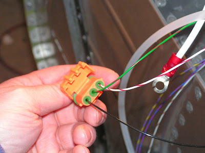
Step 3: Install the Weatherpak connector into the Manifold Pressure Sensor.

This completes page 45A-07.
Reference page 45A:08
Step 1: Remove the outer nuts and washers from the terminals on the Master Relay. But do not remove the nut laying against the relays case.

Step 2: Slip the ring terminal ,closet to the red band, of the ES Diode Master through the insulted boot and onto the right stud of the Master relay. Also slip the free end of the Battery Power wire through the same boot. Then tighten it to the relay.

Step 3: Separate the White and Orange Master Relay wire from the wiring harness. Strip the end and install a ring terminal as directed in the RV-12 airplane plans.

Step 4: Slip the unconnected ring terminal from the ES Diode Master and the Master relay wire through a insolation boot and onto the front stud of the Master Relay.

Step 5: Slip a insulated boot over the end of the WH-P154 Starter to Master Relay Cable. Connect the terminal to the left stud on the Master Relay.

Step 6: Remove the nuts and washers for the two studs on the Starter Relay.

Step 7: Find the and route the WH-P157 Battery Power Wire through the cushioned clamp on the engine mount. Strip the end and install a ring terminal.
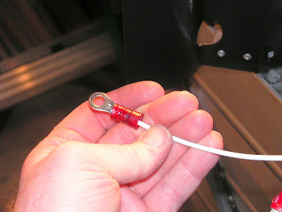
Step 8: Slip the ring terminal through a insulated boot and onto the left stud of the Starter Relay. Terminal is pictured below but is not in focus.

Step 9: Slip one end of the WH-P155 Starter Power Cable through a insulated boot and onto the right stud of the Starter Relay. Tighten the terminals down on the studs.

Step 10: Separate the spade connector crimped onto ORN and PRP wires from the engine harness. Insert the female spade connector onto the male terminal located on the lower center of the Starter Relay.

Step 11: Remove the right side mounting bolt from the Starter Relay and slip the ring terminal attached to the wire covered with Blue heat-shrink coming from the engine harness. Reinstall the bolt and washer.

This completes this entry and today's work on the RV-12 airplane's engine wiring.

