If you have just found this blog, I'm building a RV-12 airplane kitted by Van's Aircraft. It falls under the E-LSA portion of the light sport aircraft catagory. It is a very complete kit with just about everything you need; but some assembly is required:)
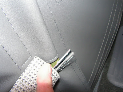
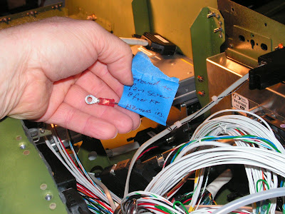
Step 1: Strip the end of the Gound wire coming out of the ELT panel switch.
Builder's note: My ground wire was 1/2" too short to attach it. So I ended up splicing an extension on it. Hopefully your mileage will vary.
Step 2: Crimp a ring terminal on to the end of the ground wire.
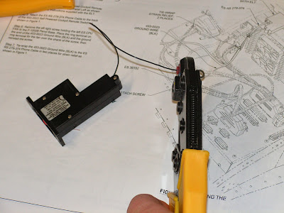
Step 3: Refer to the instructions supplied with the ELT for the installation of a battery in the Self Powered Cockpit Remote switch. Builder's note: There was already a battery installed in mine so the only thing I needed to to do is put a sticker in the Airframe log that says "Change the battery every 5 years."
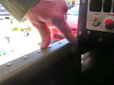
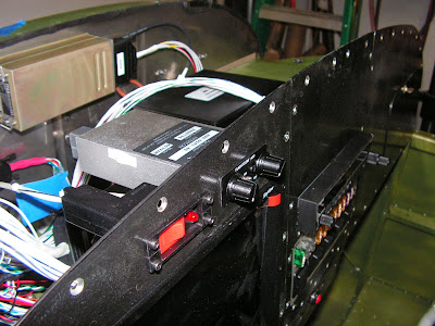
Step 4: Attach the remote switch to the Instrument Panel.
Step 5: Attach the Phone cord to the back of the Remote switch.
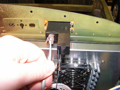
Step 6: Remove the aft right screw from the cooling fan mounted on the pilots side of the Panel Base and ground the ring terminal. This was completed on 4/28/14 and is documented in that entry. As well as the need for an extension.
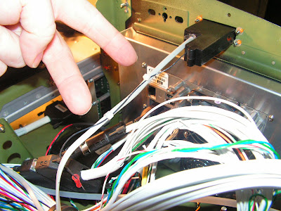
Step 7: Tie-wrap the Ground Wire to the Phone Cable in two places for strain relief.
This completes page 42C-13.
Reference: Page 42C-14
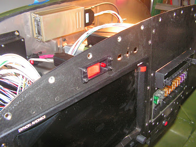
Step 1: Install the Panel Mount Stereo Intercom using the Small Intercom Faceplate. DO NOT enlarge the holes in the panel!. Builder's note: I know this seems strange , but that's what the RV-12 plans say.
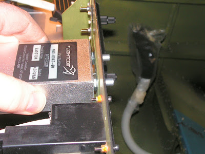
Step 2: Install the 25 pin Skyview Harness labeled "FC-403" the back of the Intercom. Route the wiring through the cushioned clamp near the cooling fan and install the other end labeled "INTERCOM" to the control module.
This completes page 42C-14.
Reference: Page 42C-15
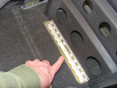
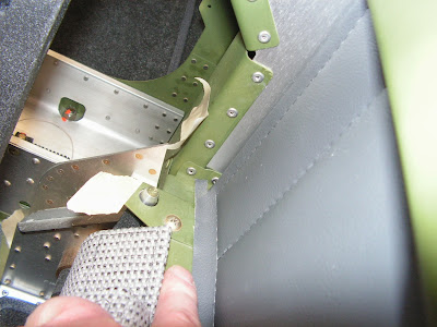
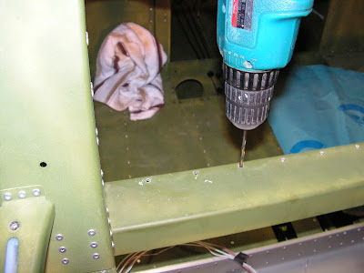
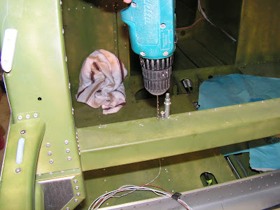
Step 1: Remove the existing rivets and then final drill #19 the hole for mounting the ELT antenna bracket. Match drill each hole for a K1000-08 nutplate.
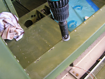
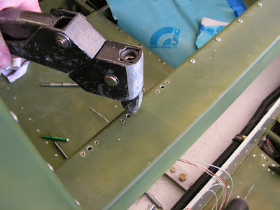
Step 2: After deburring the holes Rivet the nutplates into place.
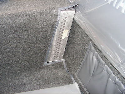
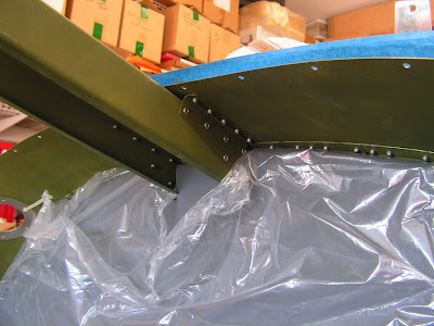
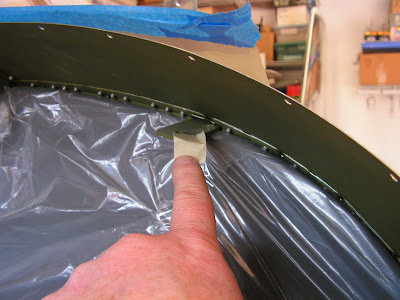
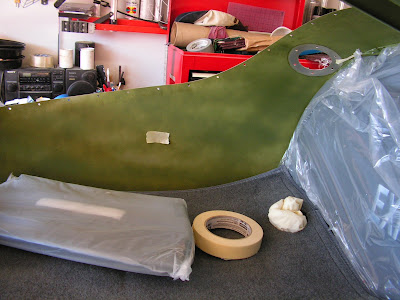
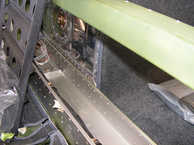
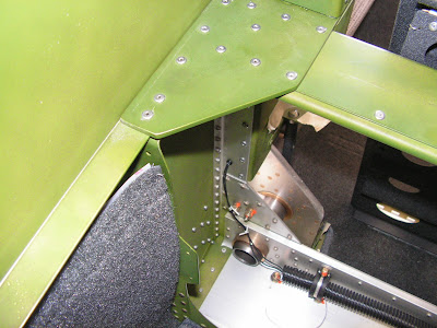
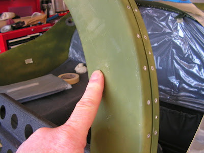
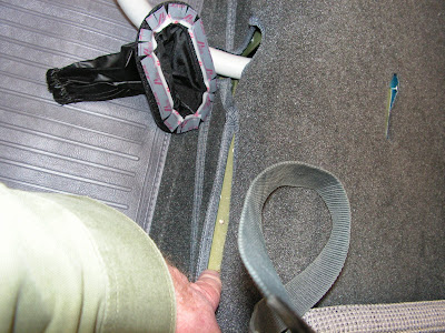
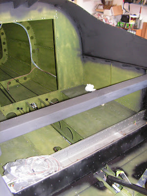
The rest of the time was spent painting the interior of the RV-12. I didn't paint the entire thing because it already has zinc chromate and I am planning on using a carpet kit. So I only painted the areas that show. Except for the anodized center section I left that bare. So I will leave you with the areas I choose to paint.