This is the next installment of the RV-12 airplane's firewall forward wiring.
Step 1: NA Top Skin was previously removed.
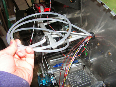
Step 2: Install the WH-00063 Rotax Fwall Fwd Harness 25-pin connector labeled "FWL FWD" to the Control Module.

Route the Fwall Fwd harness through the cushioned clamp near the CPU Fan on the base plate and through the firewall penetration.

Step 3: Install the Power Wiring harness to the back of the Power & Switch Module and route the wires through a snap bushing in the Com Support and out through the firewall penetration.
Builder's note: The two supplied snap bushings are crammed full of wires with no more room. So I added a new snap bushing in the Com support and ran the wiring through it.


Step 4: Install the Exhaust Gas Temp Harness. to the engine Monitoring Module. Running the wires through the cushioned clamp near the CPU fan and through the firewall penetration grommet.

Steps 5: NA See Step 6.
Step 6: The tube I used is long enough to span the complete distance so no splice was needed. The whole story is I melted the original tube through on a lamp when installing it in the tailcone and had to replace it. So I routed the new one through the firewall penetration.
This completes page 45A-04
Reference: page 45A-05.
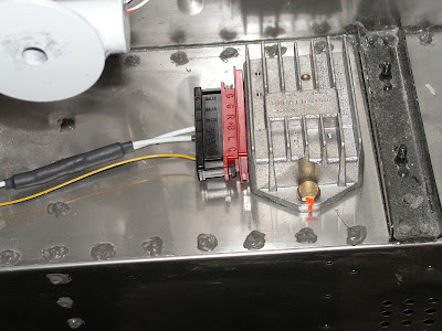
Step 2: Deburred the fuel pressure sensor bracket, prepped and painted it.
Reference: page 45A-06
Step 1: Route the Wiring through a cushioned clamp attaching it to the Engine mount.
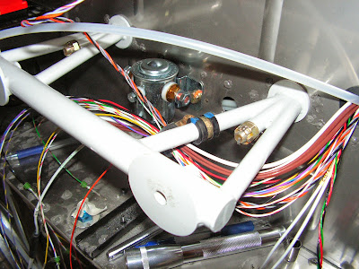
Step 2: From the Power Wiring Harness separate the W-P156 wire that splits into two wires three inches from the end. Attach a spade connector supplied with the regulator connector. Then insert them into the correct locations ensuring they are locked in place.

Steps 3 & 4: Separate the Wh-P761(YEL) wire from the wiring harness. Attach a supplied spade connector and insert in the position indicated in the RV-12 airplane plans.

Step 5: Insert the connector into the Rectifier Regulator.
This competes today's work on the RV-12 airplane. Tomorrow I will pick up where I left off.

