This entry starts the installation of the Skyview into the RV12 airplane. I should note my project started with the fuselage wiring for the Dynon D180 but has been upgraded to the Skyview EFIS system during construction. Below is a picture that gives a good idea of what the wiring looks like before starting this section.

Reference: page 42C-02
Step 1: Install the AV-50000A Control Module using blue Loctite.
Builder's note: I ended up unbolting the controller towards during the next section to adjust the potentiometers.
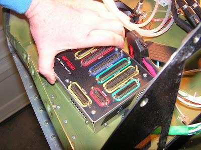
Ensure as connections are made to the control module that the correct connector goes into the correct slot. Otherwise you may let the smoke out!
Step 2: Connect the Fuselage Harness to the Control Module.

Step 3: Connect the Optional Harness labeled "OPTIONS" the the RV-12 Control Module.

This completes page 42C-02. of the RV-12 airplane plans.
Reference page 42C-03
Step 1: Install the Engine Monitoring Module to the Upper Firewall.

Step 2: Install the SV-Backup battery the the Panel Base.
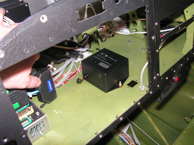
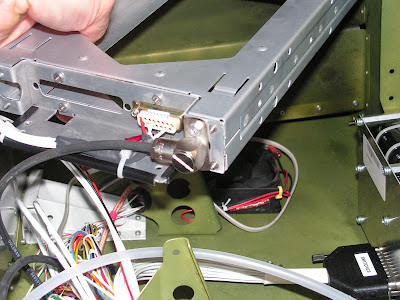
Step 3: Install the 50 pin "EFIS" connector, to the Control Module.

Install the 37 pin "EMS" to the Engine Monitor. Route the remaining harness wires through the cushioned clamp next the the fan attached to the panel base. Install the 9 pin connector "EMS" to the engine monitoring module.

Install the 3 pin Molex connector to the matching connector on the EFIS bckup battery. Arrange the two connectors and wiring that will plug into the Skyview by creating a service loop. Install the USB socket into the base panel.

This completes page 42C-03.
Reference: page 42C-04
Step 1: Install fuses in the Power & Switch Module.
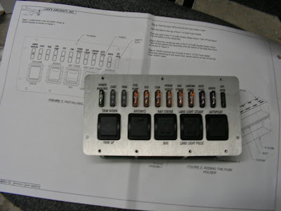
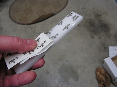
Step 2: Install the pressure sensitive label on to the fuse holder
Step 4: Insert the second set of fuses into the holder.
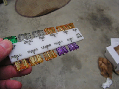
Step 3: Install the velcor to the holder and the inside of the Map Box Door.

Builder's note: I put the fussy side on the door.

This completes page 42C-04.
Reference: Page 42C-05
Step 1 & 2: Using the screws called out by Van's Aircraft, install the Power and Switch Module into the center Panel.
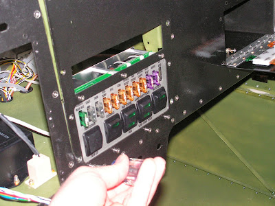
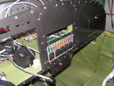
This completes page 42C-05.
Reference: Page 42C-06
Step 1: Install the Switch Module harness on the back fo the Power & Switch module. Then route it to the Control module and connect it there as well.

This completes page 42C-06.
Reference: Page 42D-17
Step 1 & 2: The 25 pin radio harness was already attached to the tray. So it just needed to be routed see Step 1 on page 42C-07.
Step 3: Install the Xpondr Ant Cable Extension onto the Transponder antenna Cable.

This completes page 42D-17.
Reference: Page 42C-07
Step 1: Route the Com radio harness through the upper snap bushing in the in the Left com Support and through the cushion clamp by the cooling fan.

Step 2: Connect the SL-40 radio wiring harness to the Control Module.

Step 3: Install the com Antenna Cable on to the back of the radio tray.
This completes today's work on the RV-12 airplanes wiring. Tomorrow is another day!

