Welcome to the chronicle of building an RV12 aircraft kitted by Van's Aircraft. This installment is part three of the upper forward fuselage. There is a GOTCHA (of sorts) with the Strut Attach angles. Others have run into the same problem, it deals with the rivet edge clearance when the holes are drilled into the fuselage longerons. More on that later, let's get to the build.
Step 1: Separate the Panel Attach Strip into left and right parts.

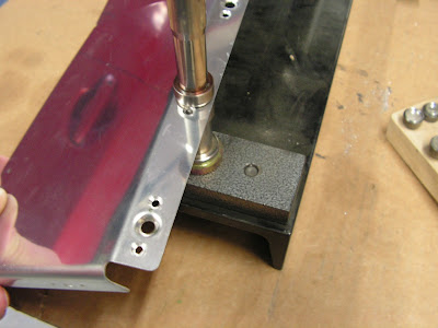
Step 2: Make the Strut Attach Angles by cutting two lengths of AA6-125X1X1 to 1 5/8 inches and drilling as shown in figure 2 on page 29A-05. Deburr. Machine countersink to two nutplate attachment holes.

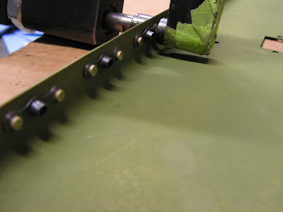
Builder's GOTCHA: Here in lies the problem. The angles pictured above look great. But when the are fitted and drilled to match the fuselage, the front rivet hole edge clearances are too small. So I made a new pair that are slightly longer on the forward dimension. They are pictured below.

NOTE: New attach angle is riveted in place with the original one being held in my hand as pictured below.

Step 3: Machine countersink the Canopy Rib flanges for nutplate attach rivets.


Dimple the rivet hole location on the canopy ribs for AN426D4 rivets and all fastener locations that will use a flush screw.
Machine countersink the Canopy Attach Doublers for AN426AD4 rivets.

Step 4: Cleco the Canopy Attach Doublers and Strut Attach Angles to the Canopy Ribs.
Final-drill 1/4 the center fastener location in the canopy attach doubler and canopy ribs that correspond to the K1000-4 nutplates.

Cleco then rivet the canopy attach doublers and strut attach angles to the canopy ribs leaving out the rivets along the bottom flanges.


Rivet on all nutplates shown in Figure 3 of the RV12 plans on page 29A-05 that attach to these parts.

Step 5: Dimple the nutplate rivet holes in the aft flange of the Panel Base and the corresponding nutplates.
Rivet nutplates to the aft flanges of the panel and Inst Stack Angles that will attach to the SV Center Inst Panel. Dimple the rivet holes in the four nutplates that mount to the web of the panel base then rivet to the panel base

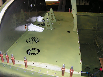
Step 6: Cleco the Panel Base to the Firewall Upper. Check that the aft edge of the panel base abuts the forward edge of the Canopy Decks and that the left and right edges are parallel to the Longerons then match-drill #30 the holes common between the panel base and the longerons. Remove the panel base and deburr the longerons.
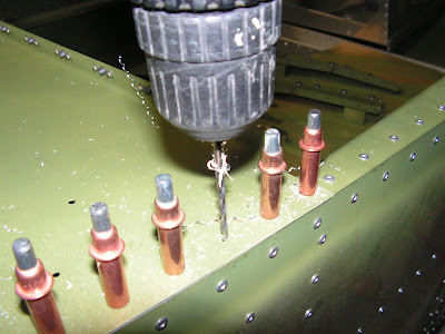

Step 7: Cleco the Canopy Ribs to the Panel Base and match-drill #30 the holes in the panel base to the Strut Attach Angles. Remove and deburr.

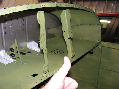
Step 8: Final-drill #30 all rivet holes in the Engine Mount Brackets then rivet them to the web of the Panel Base. Rivet the Inst Stack Angles and the Com Supports to the Panel Base. This will create the Panel Base.


Builder's Note: I transposed the Instrument Stack Angles during instillation but have since corrected the problem as pictured below.
Step 9: Slit four SB750-10 Snap Bushings and insert them in the forward flanges on the left and right Com Supports.

Insert two(un-slitted) Snap Bushing in the web of the Panel Base.
Builder's note: Because I am installing ABS-D there is an extra snapbushing to install here.

NOTE: Place the head of the fastener on the forward face of the Firewall Upper to aid in cleaning the engine compartment area.
Step 10: Rivet the Panel Base Assembly to the Firewall Upper and Longerons. Rivet on the three nutplates common to the Panel Base Assembly and the Assembly and firewall upper.


Step 11: Seal the base of the Canopy Rib Assemblies with Tank Sealant.

This completes page 29A-05 of the RV12 airplane planes. All went well just keep an eye on the Strut attach angles when making them.

