This continues the wiring on the RV-12 airplane build. Because of updates to the avionics, a number of things may have changed in the wiring instructions. My kit uses an update conversion to the Dynon SkyView. Therefore this is documentation for my airplane and probably won't match future avionic kits.
Step 1: Separate the WH-P32 (WHT/RED) and WH-P##(WHT/RED) Fan Power Wires from the WH-RV12-TUNNEL harness.

Step 2: Route the WH-RV12 Tunnel harness and WH-P33(WHT/RED) through the lower snap bushing in the F-1202K-L Inst Stack Support.

Step 3: Route the WH-RV12-Tunnel harness down through the forward most snap bushing in the center forward region of the Panel Base. 28.5 inches should remain above the panel base. Tape the tunnel harness down so that chi distance does not change as you route wires.

Builder's note: The length mentioned above will be much shorter as the Dynon SkyView adapter kit changes a number of thing. Consult the RV-12 aircraft plans before doing anything wild!
Step 4: Route the WH-P33 (WHT/RED) Fan Power Wire through the lower snap bushing in the Inst Stack Support.

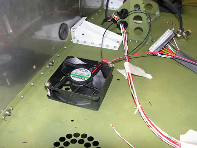
Step 5: Strip the ends of both the black and red wires coming from both CPU FANS. Crimp on ring terminals to the ends of the black wires per the hardware call-put.


Builder's Note: I used Noalox on connector to aluminum ground points to prevent future corrosion and electrical ground problems.

CAUTION: Do not over tighten the screws holding the ES CPU FANS. This can bend and then break the attach ears on the fans!
Step 6: Install both ES CPU FANs, with the left fan blowing up and the right fan blowing down. The ground ring terminal goes underneath the head of one of the screws that hold the fans in place. The flow direction of the fan can be checked by hooking the red wire to the positive terminal on a 12 volt battery and touching the black to the negative battery terminal.
Step 7: strip the ends of the WH-P32 & P33 (WHT/RED) Fan Power Wires and connect them to the red wires coming from the fan using the butt splices called out.

Step 8: Add a cushion clamp around the WH-RV12-TUNNEL harness just aft of the left CPU FAN. Loosely install the screw for adding more cables later.
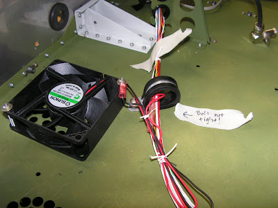
Step 9: Route the WH_RV12_TUNNEL harness through the fuel flow cushioned clamp.

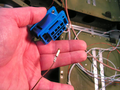
Step 10: Separate out the twisted wires WH-Q51 (BLK), WH-Q52(YEL) and WH-Q35 (RED) and strip the ends. Attach female spade commuters to the black and yellow wires and a male connector to the red wire per call-out in figure 1 on page 31-04 of the RV-12 plans.

Step 11 for (FT-60) flow sensor: Connect the WH-Q52 (YEL) to the white wire coming from the FT-60 Fuel Flow Transducer. Attach the remaining two wires to their corresponding color coming from the fuel flow transducer.

This completes page 31-04 of the RV-12 aircraft plans.
Reference page 31-05
Step 1: Route the WH-RV12-Tunnel harness through the snap bushings in the F-1202F and F-1203A Bulkheads.

Step 2: Find the WH-F57 (BRN/YEL) Stall Warn Wire and route it through the snap bushings in all the F-1215 Seat Ribs on the left side of the aircraft. Strip the end of the stall warn wire and crimp on a connector. BUILDER'S NOTE: used new connector as called out on page 31A-07.

Step 3: Lay the remaining WH-RV12-Tunnel harness through the wire notices in all three System Blocks then route though the forward snap bushing in the F-1204 Center Section Assembly.

Step 4: Find the WH-Q54 (ORN/DRN) Fuel Level wire and WH-F55(WHT) GPS Data Out wire then route them up through the upper snap bushing in the F-1204 Center Section Assembly, then into the F1204Y Wire Run Conduit and out the right end (use the string installed previously). Strip the end of the fuel level wire and crimp on a ring terminal.

NOTE: An optional ES NOISE FILTER PUMP may be installed at this time to reduce the possibility of audio noise from the fuel pump entering the audio system if installing the ES NOISE FILTER PUMP.
This completes this entry. I will be installing the OP-50 fuel pump option in the next entry.

