I am coming to an end of how much of the RV-12 aircraft wiring I can do without having the tail cone in place. My main focus is now to get the flight controls finished and the wings fitted before finish the installation of the tail cone. You may recall my wings are stored at a secondary location, so while I can easily move the fuselage front section around this is the time to do these projects.
Step 1: Install the ES AS212 12 Volt Power Outlet and the audio jack on the WH-RV12-Music harness to the F-1230A Bulkhead.
Step 2: Make the WH-B54(WHT) Power Outlet Ground by cutting a piece of 18 gauge wire 8 inches long. Strip both ends. Install a ring terminal on one end and a female spade connector on the other per the call-outs in Figure 1. Install the spade connector to the negative terminal on the back of the Power Outlet.

Reference: page 31-11
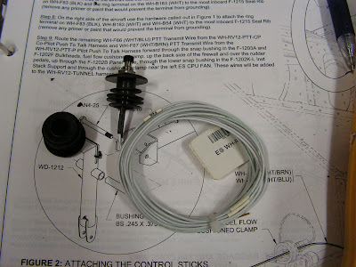
Step 1: Purchase a set of 7/8 handle bar grips from a local bike shop. Remove the plug from the end and install the grips over the end of the WD-1212 Control Sticks.
Builder's Note: I found a nice pair of foam grips at the local Bike-N-Hike store.

Step 2: Drill 1/4 inch a hole in the center of the handle bar grip plug. Remove the nut from the switch on each Push to Talk Harness switches and screw into the plug from the bottom. Screw the nut back onto the switch.
Builder's Note: In drilling the plugs I did need to drill the backside of the plugs to 3/8 inch with a unibit. Also I put a drop of thread lock on the nut to prevent them from loosening up.
Step 3: Starting at the top of the WD-1212 Control Sticks thread the Push to Talk Harnesses through and out the bottom of the control sticks. Loop wires up and tie wrap them to the shank and the bottom of tie gooseneck on the control sticks.
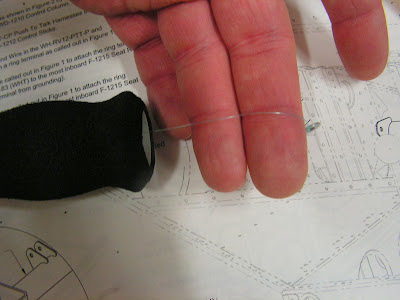
Builder's Note: I found using a small weight (i used a washer) and light test fishing leader was easier to work through the control stick and then this could be used to pull the wires through the control sticks.


Step 4: Temporarily install the Control Sticks by sliding a bushing into the stick and then a bolt to attach the stick to the WD-1210 Control Column. See Page 32-05 for more detail.

Step 5: Route the Push to Talk Harnesses through the snap bushing in the F-1215 Seat Ribs just inboard of the WD-1212 Control Sticks.
Step 6: Strip the end of each WH-F83(BLK) PTT Ground wire in the Push to Talk Harnesses. Crimp on a ring terminal called out in figure 1 (on page 31-11).
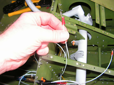
Step 7: On the left side of the aircraft use the hardware called out in figure 1 to attach the ring terminal on the WH-F83(BLK) and the ring terminal on the WH-B183(WHT) to the most inboard Seat Rib (remove any primer or paint that would prevent the terminal from grounding.

Builder's Note: I also use a conductive paste that prevents corrosion from setting in at a later time.

Step 8: On the right side of the aircraft use the hardware called out in figure 1 to attach the ring terminal on WH-F83(BLK), WH-B183(WHT) and WH-B54(WHT) to the most inboard Seat Rib (remove any primer or paint that would prevent the terminal from grounding.

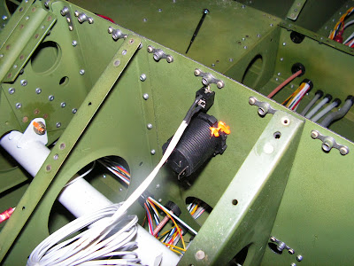
Step 9: Route the remaining WH-F66 (WHT)PTT Transmit Wire from the Co-Pilot Push To Talk Harness and WH-F67 (WHT) PTT Transit Wire from the Pilot Push To Talk Harness forward through the snap bushing in the F-1203A and F-1202F Bulkheads, fuel flow cushioned clamp, up the back side of the firewall and over the rudder pedals, up through the Panel Base, through the lower snap bushing in the Left Inst Stack Support and through the cushioned clamp near the left ES CPU FAN. These wires will be added to the Tunnel harness later.

Builder's Note: The RV-12 plans called out the above wires as white and Blue but on my harness they are only white.
This completes page 31-11. Next time I will delve deeper into the flight control installation.

