This is starting into a part of the build on the RV-12 airplane that may seem a little disjointed. I will try not to jump around too much, but with the update in the avionics and changes in the kit it is unavoidable. For example Steps 1 - 5 on page 31-02 deal with the wing interconnects, but are the old design and have been superseded in a different section.
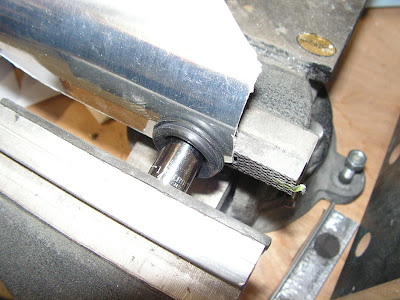
Step 6: Modify a grommet to be used for firewall penetration. Using a socket and a vise, squeeze the penetration. Using a socket and a vise, squeeze the grommet called out until the socket shears through the grommet(this will be accompanied by a distinct crunching sound.)
Reference page 31-03
Step 1: Insert the modified rubber grommet (from the previous step) into the Firewall Upper penetration.

Step 2: Cut a 36 inch length of DUCT NT 5/8 to make the Wire Run Conduit. Cut a 7/16 diameter hole in the wire run conduit for the wires coming from the top center of the Center Section Assembly. To help pull wires through later, add one string going from the hole to the left end of the conduit, one from the hole to the right end and one going from one end to the other. Leave enough string at each end.
Builder's note: I used heavy fishing line with good results.

Step 3: Using the clamps and hardware called out in the detail view in the right side of figure 1 on page 31-03. Install the Wire Run conduit. Center the wire run conduit about the centerline of the aircraft with the hole cut in Step 2 over the snap bushing in the Center Section Assembly.

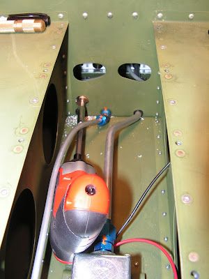
Builder's note: my airplane cam with the FT-60 flow transducer.
Step 4: Remove the forward most bolt. holding the FT-60 Fuel FLow Transducer. Final drill 1/4 the cushion clamp called out, then slide it over the bolt and reinstall the bolt.

NOTE: When routing cables and wires some snap bushings may need to be removed and the wire or cable passed through the hole. Slit the snap bushing, place it over the cable and snap the bushing back into the hole.
Step 5: Route the straight BNC fitting on the WH-RV12-SL-ANT and WH-RV12-TX-ANT down through one of the snap bushing in the Panel Base, over the rudder pedals, and through athe fuel flow cushioned clamp. Continue to route the WH-RV12_SL-ANT through the snap bushing in the F-1202F and F-1203A Bulkheads. Lay the cable through the wire notches in all three System Blocks. Route the cable through the snap bushing in the front of the F-1204 Center Section Assembly.

Builder's note: To get the BNC connectors past the rudder pedals I needed to loosen the center clamp as pictured below.
Step 6: Route the Phone Cable through the right end of the Wire Run Conduit, then down through the wire run hole in the top of the F-1204 Center Section Assembly (16 inches should remain protruding from the right end of the wire run conduit.) Slit then insert a snap bushing in the top of the F-1204 Center Section Assembly. Route the cable forward through the same route used by the WH-RV12-SL-ANT. ROute the cable through the snap busing in the Inst Stack Support.


Reference: page 53-03
These holes are added for the ADS-B option.
Step 1: Drill 3/4 and deburr a new wiring hole in the F-1204A Bulkhead as shown in figure 1 on page 53-03.

Step 2: Drill 3/4 and deburr a new wiring hole in the F-1204D Bulkhead as shown in figure 2. Install snap bushings.
Reference: page 53-05
Step 1: Use a bench vice or hand seamer to bend the Wire Cover Plate flanges as shown in figure 1.

This competes this entry for the RV-12 aircraft build.

