This is a continuation of the wiring for the RV-12 aircraft I'm building. Again there are a number of changes because of updating to the Dynon SkyView. For example all of the spade connectors for the autopilot servos will be installed and then replaced with new molex connectors.
Step 1: Using the callouts in figure 2 on page 31-08 of the RV-12 airplane plans, drill #30 a pilot hole for the outside air temperature probe. Use a unibit to final-drill this hole to 3/8.
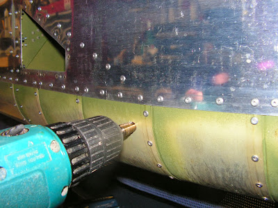
Step 2: Install the WH-RV12-OAT harness in the hole created in Step 1. Route the wires back through the snap bushing in the Seat Ribs to the center of the aircraft.

This completes page 31-08.
Reference: page 31-09
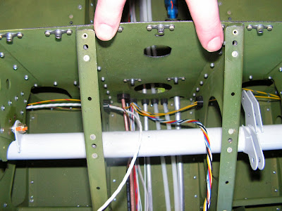
Step 1: Route the WH-RV12-OPTIONAL harness over the rudder pedals, through the fuel flow cushioned clamp and through the snap bushings in the F-1202F and F-1203A Bulkheads.

Step 2: From the WH-RV12-OPTIONAL harness separate out and route the WH-L72(YEL/RED) wire through the snap bushings in the Seat Ribs on the left side of the aircraft. Separate out the WH-L73(YEL) and WH-L88(YEL/BLU) wires and route them through the snap bushings in the seat ribs on the right side of the aircraft.
Step 3: Make and label the WH-B184(WHT) Nav/Strobe Power Wire by cutting 53 inches of 18 gauge wire and striping each end.
Step 4: ON the left side of the aircraft crimp both the WH-B184(WHT) and WH-L72(YEL/RED) wires together in the same female spade connector.

Builder's note: This spade connector is used in the new updates but the old F-1270B Assy will be replaced. See page 31A-08 for the updated assembly.

That completes this entry on the wiring for the RV-12 airplane. The best advice I have when it comes to wiring is go slow, focus on each step you are doing and document, document document!

