Van's Aircraft issued a service bulletin because of cracks developing in the Oil Tank Bracket on some airplanes. They did send the parts out with the notice which is great customer service. So with this posting I will continue with the Upper fuselage and installing the SB 13-04-05 service bulletin.
Reference: SB 13-04-05
Steps 1-5 Do not apply as this RV12 is still under construction.
Step 6: Using the dimensions in Figure 4 (from the service bullitin) layout then drill #30 the hole pattern shown into the F-1201E-L & -R Brackets.
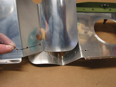
Step 7: Deburr the edges of the F-1201GMOD rib. Draw a centerline on the four forward facing rib flanges. Orient the rib, flanges facing up as shown in Figure 4 so that the centerlines drawn on the flanges are centered on the holes drilled in the previous step. Match-Drill #30 the holes in the F-1201E-L & -R into the rib. Remove and Deburr the rib. Prime the rib if desired. Rivet the rib to the brackets using the rivets called out in Figure 4.


These next three steps will be completed after I get an engine and a log book!
Step 8: Re-install the oil tank and battery. Add oil to the system. Re-install the lower and upper cowlings.
Step 9: Complete Rotax SI-912-018 oil system purge procedure.
Step 10: Make a logbook entry indicating compliance with this Service Bulletin.
Reference: page 29A-06
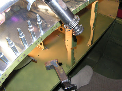
Step 1: Dimple the three holes in each Oil Tank Side Bracket that will receive flush fasteners as called out by Van's Aircraft.

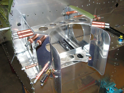
Step 2: Rivet the Oil Tank Side Brackets to the Firewall Upper. Rivet the Battery Mount Brace to the firewall upper.

Step 3: Rivet the Battery Mount Brace, Battery Mount Angles and Oil Reservoir Brace to the Oil Tank Side Brackets.
Builder's note: This is also when I installed the new SB bracket

Step 4: Cover the head of each rivet on the firewall with a thin layer of fuel tank sealant.

Step 5: Make the Clip from provided AS3-025 aluminum as shown in figure 2 on page 29A-06 of the RV12 plans. Match-drill #40 to the F-1240B Cover Plate. Test fit the clip to the fuselage to determine which side goes up then deburr and dimple the rivet and screw holes in the clip and the cover plate then rivet the clip to the cover plate using the rivets called out.


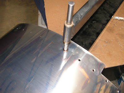
Step 6: Carefully curve the forward edge by hand. The upper forward fuseage skin should be curved enough that the forward edge presses against the Upper Forward Doubler when installed.

Step 7: Final-drill #19 then dimple the holes in the Upper Forward Fuselage Skin.

Step 8: Screw the Upper Forward Fuselage Skin to the F-1201A Assembly, Fuselage Side Skins and the Canopy Ribs.
Screw the F-1240B Assembly to the upper forward fuselage skin.


Step 9: Dimple the nutplates called out and the rivet locations in the Panel Attach Strips Rivet the nutplates to the panel attach strips.

Step 10: Start from the inboard and work out clecoing then riveting the Panel Attach Strips to the Upper Forward Fuselage Skin.
This completes page 29A-06 and the service bullitin SB 13-04-05 for the RV-12 aircraft. So long until next time.

