These next few sections for the construction of the RV-12 aircraft are proving interesting to document. Because of the installation of the Dynon Skyview three different wiring section are all interconnected. Also there are a number of new options and revisions. Not to mention having assemblies of the airplane stored at two different locations. So we will see how this all turns out!
Step 1: Tap the hole in each of the Fuselage Pin Stoppers as shown in figure 1 on page 30-02 of the RV-12 plans.
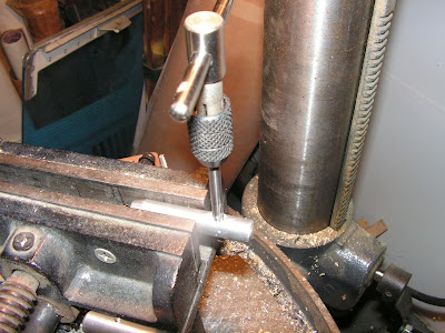
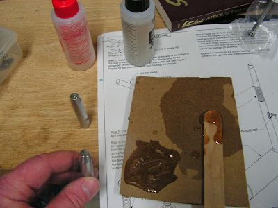
Step 2: Insert the Magnet all the way to the bottom of the hole in the Fuselage Pin Stopper then fill the remainder of the hole with epoxy and allow it to set. Repeat for the second magnet and fuselage pin stopper.
Step 3: Cut two 1/4 inch pieces from the PT 1/4OD clear tube and slip one piece inside each bushing.
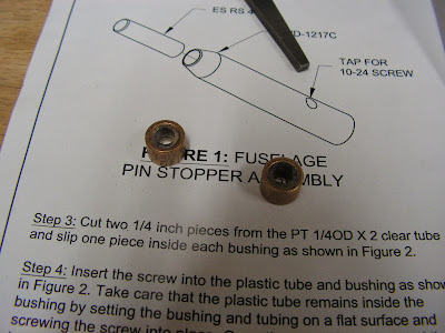
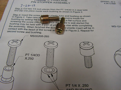
Step 4: Insert the screw into the plastic tube and bushing. Take care that the plastic tube remains inside the bushing by setting it on a flat surface and screwing the screw into place. Once the screw is well stared the bushing may be held with pliers or a vise. When finished the bushing and plastic insert will be in contact with the head of the screw. Repeat on the second screw.
Builder's note: I painted the fuselage pins before completing to the next step.
Step 5: Install the Spring and Fuselage Pin Stopper into the Fuselage Pin. Apply a small amount of Loctite #242 to the screw threads and insert the screw. When properly installed the fuselage pin stopper can be moved up and down by applying pressure to the screw on the side of the fuselage pin assembly.
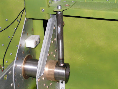
Repeat the process for the second fuselage pin, but insert the screw on the opposite side of the fuselage pin assembly.
With these pins built it is time to move the fuselage front section to the warehouse where the wings are stored for fitting.

