Last time I promised more fun to come and here it is! During construction of my RV-12 aircraft Van's Aircraft changed from the Dynon D180 to the newer Skyview EFIS. As I had already received my finishing kit my conversion falls under the Skyview Update Instructions, but is being updated during construction. Because of this I find I am having to jump between few different sections. Because of this there is a really good chance many of the steps I post will have no bearing on other RV-12 kits.
So, last entry was dealing with the insulation of the Forward Upper Fuselage. Because of the new Skyview system I needed to modify the instrument shelf to match Van's Aircraft new kit standards before moving forward with Section 29A.
Also I have elected to install the ABS-D option at this time as well.
Note page 42D-02, deals with removal of the D180 and assumes the aircraft is finished. There are a few applicable steps to my project but these will be referred to as they come up in other sections.
Step 1: NA as this piece is not installed in the airplane. Clamp a small board or metal angle across the bottom aft edge of the F-1202B Panel Base to prevent it from getting buckled/damaged.
Step 2: NA not installed Remove the rivets that attach the F-1202J-L & -R Stack Angles, and F-1202K-L & -R Inst Stack Supports to the F-1202B Panel Base. See Page 29-04 Figure 4 of the RV12 plans.
Remove the rivets attaching the F-1202A-1 Instrument Panel to the F-1202B Panel Base. See Page 29-07 Figure 1.Remove the F-1202A-1 Instrument panel.
NOTE: In the SkyView installation the connection of the pitot and static lines to their pressure transducers is made in the tailcone. The plastic tube running from the forward fuselage to the tailcone was previously used as the Static Line has now become the Aft Pitot Line.
Step 3: NA not installed Pull the Aft Pitot Line back through the F-1202B Panel base and all the bulkheads back to the area of the fuel pump behind the F-1204 Center Section Assembly.
NOTE: Making holes and cutouts in this section will result in metal debris that must be removed fromthe aircraft. Layout a cloth beneath the working area to help with cleanup. Deburr all holes after drilling. See Section 5B.
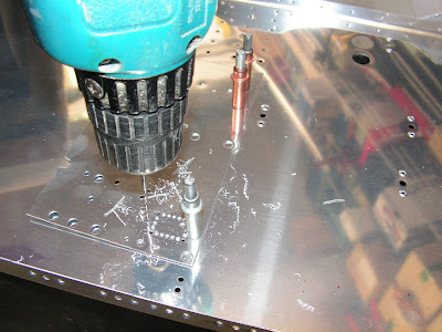
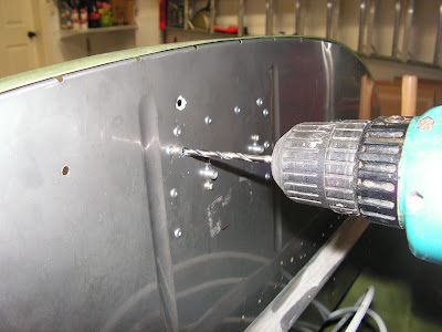
Step 4: Final-Drill #27 the center six holes in the F-1202B Panel Base. See Figure 2. Draw a center line across the center of the six #27 holes to help in orienting the nutplates for the next step. See Figure 2 on page 42D-03.

Step 5: Use a #6 screw to position a nutplate as a drill template at each of the six holes final-drilled in Step 2. Use the center line to show when the nutplate is horizontal. Match-Drill #40 each nutplate's attach holes into the F-1202B Panel Base. Cleco the first nutplate attach hole before match-drilling the second hole.


Step 6: Dimple the 12 nutplate attach holes made in Step 3.

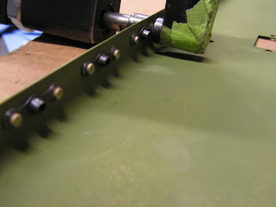
Step 7: Dimple then rivet nutplates to the F-1202B Panel Base as shown in Figure 1.
Builder's note: The picture below was completed later out of sequence.
This completes page 42D-03
Reference: page 42D-04
NOTE: Beginning on this page the use of the F-00011 Skyview Template for adding required holes is depicted. If your kit was supplied with parts already having the holes you are instructed to make using the template, ignore that step and continue.
The F-00011 SkyView Template has many holes. This could become confusing because only a few holes in the template are used for any given step. Before drilling a set of holes, study the plans carefully and mark the holes to be drilled on the template. When drilling is complete remove the marks on the template with solvent before moving on to the next drilling operation.
Step 1: Cleco the F-00011 SkyView Template to the two referenced rivet holes in the F-1202B Panel Base as shown in Figure 1.
Step 2: Match-Drill #30 the two locations indicated in Figures 1 and 2 on page 42D-04.
Step 3: Remove the F-00011 SkyView Template.
Step 4: Final-Drill #19 the two #30 holes drilled in Step 2.

This completes page 42D-04
Reference: page 42D-05
Step 1: Cleco the F-00011 SkyView Template to the two referenced rivet holes in the F-1202B Panel Base as shown in Figure 1 on page 42D-05 of the RV-12 airplane plans.
NOTE: If a tool with a small diameter rotating cutting disk is available, drill only the four corner holes of the rectangular pattern.
Step 2: Match-Drill #40 the hole pattern shown in Figures 1 and 2. Cleco after drilling the first hole to maintain alignment.
Step 3: Remove the F-00011 SkyView Template.
Step 4: Remove material from the F-1202B Panel Base in the shaded area shown in Figure 3. A small side cutters can be used to clip the material between each hole, or cut with small cutting disk. File the edges smooth.


Step 5: Final-Drill #30 the two holes indicated in Figure 3 on page 42D-05 of the RV12 plans..

This completes page 42D-05.
Reference: page 42D-06
CAUTION: Use care when drilling through the drill guide to prevent damage to the brake reservoir and brake lines (if installed).
Step 1: Position the ES-50029 AV-50000 Drill Guide as shown in Figures 1 and 2. Measure from the fan to the drill guide as shown in Figure 2 on page 42D-06 of the Rv-12 aircraft plans.Make sure the fwd edge of the drill guide is parallel with the aft surface of the firewall.
Step 2: Match-Drill #30 the four corner holes shown in Figure 1 from the ES-50029 AV-5000 Drill Guide into the F-1202B Panel Base. Cleco each hole as you drill.
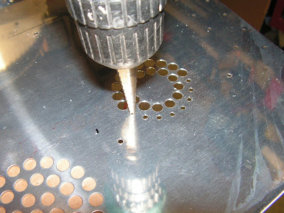
Step 3: Match Drill #30 the circular pattern of holes from the ES-50029 AV-50000 Drill Guide into the F-1202B Panel Base. Remove the AV-50000 drill guide. Use a step drill to enlarge the #30 holes in the the circular hole pattern to 5/16.

Step 4: Final-Drill #27 the four #30 holes drilled in Step 2.

This completes page 42D-06.
Reference: page 42D-07
NOTE: When drilling stainless steel (F-1201A Firewall Upper) use a lubricant such as BOELUBE on bits. During the drilling process firmly hold a block of wood on the opposite side of the Firewall Upper from the location being drilled.
Step 1: Align the F-00011 SkyView Template to the F-1201A Firewall Upper by placing the holes in the template over the rivet heads in the firewall as shown in Figures 1 and 2 on page 42D-07 of Van's Aircraft plans.
Step 2: Match-Drill #30 the three locations indicated in Figures 1 and 2. Cleco each hole as you drill.

Step 3: Remove the F-00011 SkyView Template.
Step 4: Final-Drill #19 the three #30 holes drilled in Step 2 on page 42D-07 of the RV12 aircraft plans.
This completes page 42D-07.
Reference: page 42D-08
Step 1: NA not installed; Remove the cushioned clamp which holds the fuel pressure sensor (if installed) from the firewall. See Page 45-02, Figure 3.
Align the F-00011 SkyView Template to the F-1201A Firewall Upper by placing the holes in the template over the rivet heads and bolt hole in the firewall as shown in Figures 1 and 2 on page 42-08 of the RV 12 plans.
. Step 2: Match-Drill #30 the four locations indicated in Figures 1 and 2. Cleco each hole as you drill.
Step 3: Remove the F-00011 SkyView Template.
Step 4: Final-Drill #12 the four #30 holes drilled in step 2.

Step 5: NA will be done during firewall forward installation. Re-install the cushioned clamp and fuel pressure sensor to the firewall as shown on Page 45-02, Figure 3.
This completes page 42D-08.
Reference: page 42D-09
Builder's note: most of the steps on page 42D-09 are repeated on page 29A-04. The exception is step 4 list below.
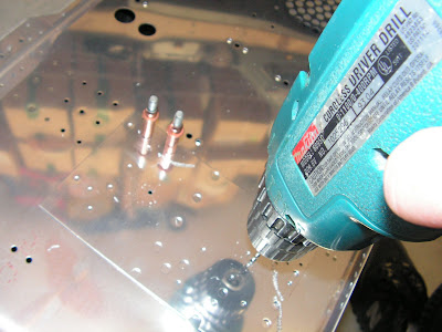
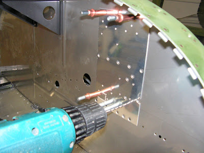
Step 4: Cleco the F-00027-L & -R Com Supports to the F-1202B Panel base as shown in Figure 3 on page 42D-09 of the RV12 airplane plans. Match-Drill #30 the most forward hole in each com support into the panel base as shown in Figure 3. Remove the com supports and deburr the match-drilled holes in the panel base.

Builder's note: I also performed the step on page 53-02 for installation of the ABS-D as this time. It is the drilling of an additional wire routing hole in the instrument shelf as pictured below.s completed all the applicable instructions on page 53-02.

This completes page 42D-09.
Reference: page 29A-04
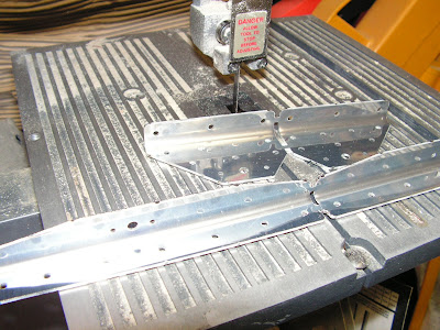
Step 1: Separate the F-00026 Inst Stack Angle into F-00026-L & -R Inst Stack Angles as shown in Figure 1.

Step 2: Machine countersink all the .098 diameter holes in the F-00026-L & -R Inst Stack Angles to fit the head of an AN426AD3 rivet. See Figure 2 to determine which surface to countersink.
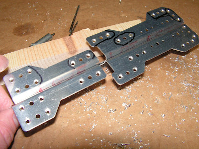
Step 3: Install nutplates on the F-00026-L & -R Inst Stack Angles in the locations shown in Figure 2. Note that there are two locations on each inst stack angle which do not have nutplates installed.

Step 4: Separate the Canopy Attach Doubler into the left and right parts.
Step 5: Separate the Battery Mount Angle into the left and right parts.
Step 6: Machine countersink the rivet holes in the Battery Mount Angles and attach nutplates.


This has been a long entry but it is nice to have it all documented. If you find yourself jumping between sections come up with a good system to stay organized and take it one step at a time. I will not be returning to section 42D until sometime later in the build.

