Today is more fun, with the wiring on the RV-12 aircraft kitted by Van's Aircraft. There is a GOTHCA (of sorts) in steps 5, 8 & 11 on page 31-09. The spade connectors mentioned in these steps have been replaced with new connectors refer to on page 31A-08
Step 5: Route the WH-184(WHT) Nav/Strobe Power Wire through all the Seat Ribs to the right side of the aircraft and crimp on a connector (See page 31A-08 for the new connector design). Secure the connector on the new wing wiring assembly on the right side of the aircraft. Adjust the wire so that there is an equal amount of slack on each end.

Step 6: Separate from the WH-RV12-OPTIONAL harness the group of seven twisted wires, strip the ends, then route them through the snap bushings in all but the most outboard Seat Rib on the left side of the aircraft. Route the seven twisted wires through the rectangular opening in the second to mot outboard seat rib on the left side of the aircraft as shown in figure 1 on page 31-09.

Step 7: Find the supplied WIRE AUTOPILOT SERVO seven stranded wire in the kit and trim to 85 inches to create the WH-B170 Autopilot Harness. Strip the wires on one end.
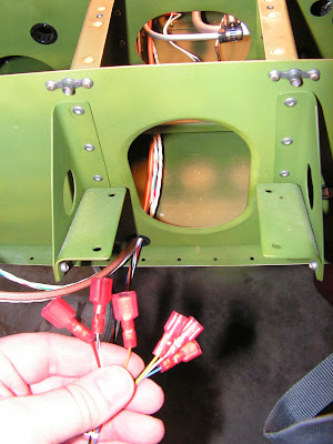
Step 8: Matching colors, crimp together in paris the same connectors BUILDER'S NOTE: Refer to page 31A-08 for new connectors! I used the old one and then had to cut them off. YEL, BLU, WHT and BLK wires from the seven twisted wires in the WH-RV12-OPTIONAL harness and seven twisted wires in WH-B170 Autopilot Harness.
Matching colors, crimp together in pairs in the same connectors the remaining RED, ORG and WHT/BLK wires from the seven twisted wires in the WH-RV12_OPTIONAL harness and the seven twisted wires in WH-B170 Autopilot Harness.

Route the WH-B170 Auto Harness back through the rectangular hole, through the snap bushings in the Seat Ribs to the center of the aircraft. Add a Plastic Tie 4.5 inch in the hole just forward of the rectangular opening (see figure 1 page 31-09) going around the wires and back through the same hole into itself.

Step 9: Create and label two WH-B183 (WHT) Wing Ground Wires from 18 gauge wire. Strip one end of each and attach an updated connector from page 31A-07. Each will be attached to the new wing wiring connector. in section 31A. Route the wires inboard through the snap bushings in the Seat Ribs. Strip the routed end of the wire and crimp on a ring terminal per the callouts in figure 1 on page 31-09. This ring terninal will be attached to the inboard most seat rib later.

Builder's Note: One nice way to label wires is use white shrink tube and a fine Sharpie marker. Write the number on the tube and then shrink it to the wire.


Step 10: Lay the WH-RV12-OAT harness and WH-B170 Autopilot Harness into the System Blocks. Route both through the Center Section Assembly, through the cushoined clamp attached to the fuel pump and the snap bushings in the F1206A and F-1207B Bulkheads.

Step 11: Strip the ends of the seven WH-B170 Autopilot Harness wires. Crimp on connectors. Builder's note: Use page 31A-08 as a guide to the new molex connector to be used. Don't use the spade connectors and then cut them off as I did!
This completes page 31-09 and this entry of the build on the RV-12 until next time.

