This entry is a continuation of the installation of a firewall stiffener mod produced by Vans Aircraft for the RV-12 ELSA airplane.
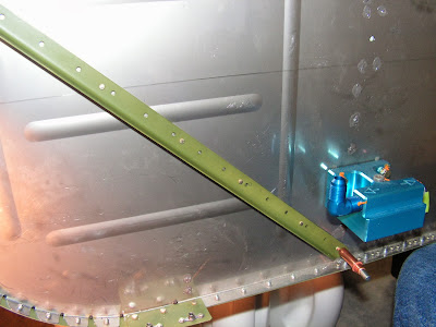
Step 2: Cleco the lower end of the Stiffener Assembly to the Firewall Bottom at the #30 hole drilled out eariler.
Rotate the Stiffener Assembly into the upper corner of the firewall bottom until the upper-most corner of the assembly is about coincident with the tangent of the firewall radius. Spacers should not contact the firewall stiffening deads.
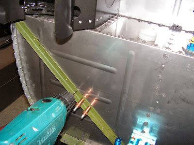
Step 3: Match-drill #30 the Firewall at the upper-most hole called out. Insert a celco into this hole.
Match-drill #30 the firewall bottom using the remaining #30 holes in the Stiffener Assembly as a guide. For best results begin near the midpoint and insert clecos along the way. Remove the Stiffener Assembly and deburr the holes in the firewall.
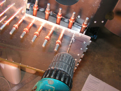
Step 4: Rivet the Stiffener Assembly to the Firewall using rivets called out, place the manufactured heads on the firewalls' fwd side.

Step 5: NA Install landing gear bolt removed previously.
This completes page 54-03.
Reference: page 54-05
Step 1: Slide a piece of thin steel between the Fuselage Side Skin and the Fwd Skin Stiffenr then cut off the stiffener to the dimension shown on page 54-04 figure 1 of the RV12 airplane plans. Use A cutting wheel in a die grinder.
Builder's note: I tried this step as written and then just drilled out the remaining rivets holding the stiffener. Removed the part from the fuselage and trimmed it as required. It was much easier than standing on my head leaning over the edge of the fuselage.

Step 2: Cleco the MOD-R & -L Skin Stiffener to the bottom surface of the Firewall Shelf using the twp #30 drilled out rivet holes.
Builder's note: I used the aluminum angle sharppened on one end to shave some of the firwall sealant out of the corner, being careful not the scratch the fuselage skins or firewall.

Drill four #30 holes through both shelf and stiffener from above at the four new hole locations marked earlier.
Remove the angle, clean out any chips or burrs and cleco at all six hole locations.

Step 3: Match-drill #30 the Fuselage side skin using the MOD Skin Stiffener holes as guides. Make sure the aft end of the angle is properly positioned using the dimension then drill the aft-most hole first. Insert clecos along the way.

This completes page 54-05.
Reference page 54-06.
Step 1: Lay out rivet locations at the fwd end of the 1295 MOD Skin Stiffeners by drawing a line on the outside of the Fuselage Side Skin using thee row of rivet holes drilled in the previous step.
Mark off the hole locations using the spacing called out on page 54-06 of the RV12 planes. Final-drill #30 through both skin and MOD Skin Stiffener at the new hole locations, inserting clecos along the way. Disassemble and deburr.
That's it for todays work.

