Another day of installing and updating the wiring in the RV-12 airplane. It is funny but I think this RV-12 has as much wiring running through the plane as my RV-10, however the RV-10 had a lot more wire in the instrument panel. Of course it had a boat load of avionics in the panel!
Step 3: NA Make the WH-B148 (WHT) Power Outlet +V by cutting a piece of 18 gauge wire 84 inches long. Label the wire. Strip one end and crimp on a female spade connector as shown in Figure 1. Install the spade connector to the positive terminal on the back of the ES AS212 12 Volt Power Outlet.
Builder's note: The step above will be replaced with part P350 on page 42D-22. So I didn't install the WH-B148
Step 4: Separate the WH-RV-12-HEADSET harness into pilot and co-pilot harnesses. The co-cilot harness is one inch longer.
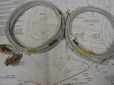
Step 5: Remove the F-1270B ASSY and install the pilot and co-pilot jacks from the WH-RV-12-HEADSET harness into the F-1226-L & -R Seat Ramp Floors.
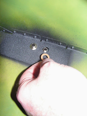
Builder's note: The insulating washers are only used on the small ID mic jacks while the headphones are grounded against the airframe.
Step 6: Route the pilot and co-pilot harnesses from the WH-RV-12-HEADSET harness inboard through all the F-1215 Seat Ribs.

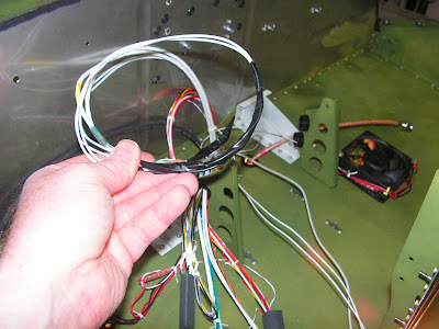
Step 7: Route the pilot and co-pilot harnesses from the WH-RV-12-HEADSET harness, WH-B148 (WHT) (Builder's note: B148 will be replaced with wire P-350) and WH-RV12-MUSIC harness together forward through the snap bushings in the F-1203A and F-1202F Bulkheads, through the fuel flow cushioned clamp, up the aft side of the firewall, over the rudder pedals, and up through the fwd snap bushing in the F-1202B Panel Base.
Step 8: NA Route the pilot and co-pilot harnesses from the WH-RV-12-HEADSET harness through the snap bushing in the F-1202K-R Inst Stack Support. Label the harnesses pilot and co-pilot. These wires will be hooked up to the intercom in the Avionics Kit.
Builder's note: The step above has been updated with the SkyView system see page 42D-20 step 5.
Step 9: NA see Builder's note above on step 3 Route the WH-B148 (WHT) through the lower snap bushing on the F-1202K-L Inst Stack Support then out through the grommet installed in the F-1201A Firewall Upper on Page 31-03.
Step 10: Route the WH-RV12-MUSIC harness through the lower snap bushing on the F-1202K-L Inst Stack Support and through the cushioned clamp near the left ES CPU FAN. These wires will be connected to the WH-RV12-TUNNEL 37-pin d-sub connector later in this section.

Step 11: na THESE WILL BE INSTALLED IN SECTION 31B Install the F-1270B ASSY per the call-outs on Page 31-2, Figure 5.
NOTE: Audio jack and resistors not provided in kit.
Step 12: If audio output to a video camera is desired add a Ø1/4 hole below the headphone jack with two extra wires coming out (shown on Co-Pilot side in Figure 1). Slip on a long piece of heat shrink over each of these wires then solder a resistor to the end of each. Solder each resistor to separate terminals coming from the back of the audio jack. Slide the heat shrink over the whole assembly then activate the heat shrink. Install the audio jack in the Ø1/4 hole.


Builder's note: I completed this step before installing the co-pilot head phone jacks as I do want a video camera audio jack in the airplane.
This completes page 31-10 of the RV-12 airplane plan manual.

