Today I started off with a unhappy discovery on the RV-12 airplane.
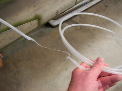
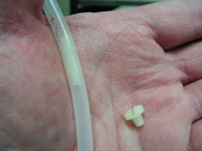
I'm not sure when it melted but above is pictured what is left of my pitot tube. So I decided to replace it all the way from the AHARS unit in the tail up to the firewall. The good news is I will have no splices in it as the updated for the Skyview EFIS system had a splice in the tailcone and at the instrument panel. The update used the old static line that ran from the tail to the panel.
It was much easier to replace than I originally though as I used a 8/32 nyolon bolt to threat the two tubes together and as I pulled the old one out I also pulled the new one in.
Step 1: Route the remaining wires of the WH-RV12-TUNNEL harness back thorough the F-1206A and F-1207B Baggage Bulkheads.
Builder's note: This was completed before I attached the tailcone.
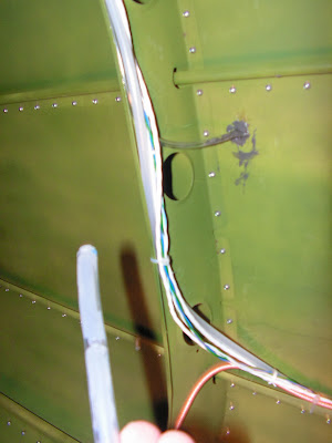
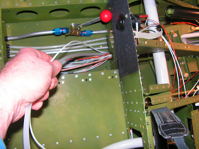
Step 2: Route WH-P30 Trim Wires and Static Line from the tailcone forward through the F-1207B and F-1206A Bulkheads, fuel pump cushioned clamp, F-1204 Center Section Assembly, F-1276C Systems Blocks, F-1203A and F-1202F Bulkheads, fuel flow cushioned clamp, around the back of the rudder pedals and up through the F-1202B Panel Base.
Step 3: NA see section 42D for the update on this step. Route the WH-RV12-OAT harness and WH-RV12-TUNNEL harness through a snap bushing in the F-1207D-L Baggage Bulkhead Channel. Slip the ES HST 3/16 X 2" Heat Shrink over the ends of the wires. Insert the pins on the ends of both wiring harnesses through the heat shrink and into the ES 205203-3 9-Pin D-Sub Female connector according to Figure 2. Check with a gentle tug that each wire has snapped into place. Center the ES HST 3/16 X 2" Heat Shrink around the location where the wires will exit the ES 9 PIN BSHELL. Activate the heat shrink.
Step 4: NA Following the routing of the Static Line, route the harnesses attached to the 9-Pin D-Sub up to the top center of the F-1208 Fuselage Frame, replacing plastic tie wraps as required. br/>
This completes page 31-12.
Reference page 31-13
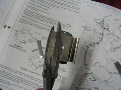
Step 5: Trim the flanges of the Over Rudder Wireway.
This completes today's work. Until next time!

