With the main gear installed on the RV-12 airplane kit, it's time to attach the empennage and finish the flight controls and linkages. So today starts the attachment of these. The plan is to leave them attach until needing to remove them for final painting.
Reference: page 11-02
Step 1: Remove the Lower hinge and hardware form the Vertical stabilizer Assembly.
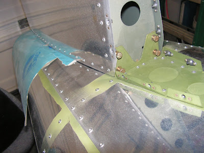
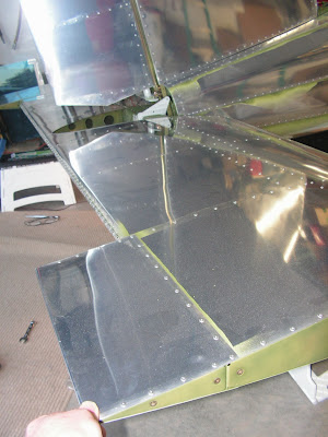
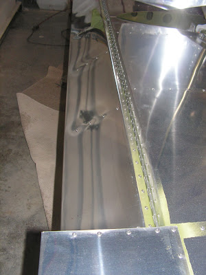
Step 2 & 3: Place paper between the V-Stab and the top of the tailcone to prevent scratching the skins. Install the four lower bolt rear spar. Also installed the front hardware on the front spar as called out by Van's Aircraft in the RV-12 plans.
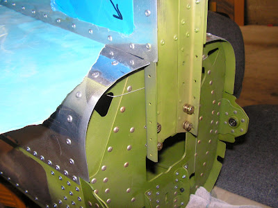
Builder's note: The bolt are not tightened until the next step.
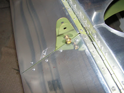
Step 4: Install the Lower Hinge and tighten all the attachment bolts enough to prevent movement of the V-Stab assembly.
Step 5: Install the rudder onto the V-Stab.
Builder's note: I need a slightly different combination of washers so as not to sideload the hinges. These I noted on the plans for future reference.
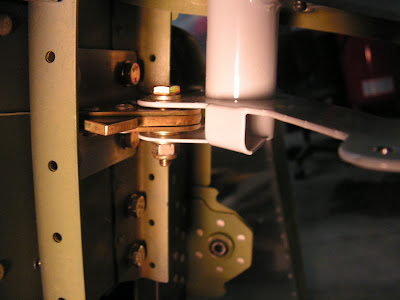
Builder's Side Note: In the picture above, there should be rivets installed in the 10 rivet holes on the sides of the V-Stab Spar. These rivets were installed after this picture was taken.
Step 6: Check rudder for full moventand free travel.

This completes page 11-02.
Reference: page 11-03
Step 1: Remove the two AN4 bolts used to locate the "glued washers" on the stabilator hinge brackets. Also mark the "top" of the Counterbalance Arm. Remove the counter balance for the RV-12's Stabilator.
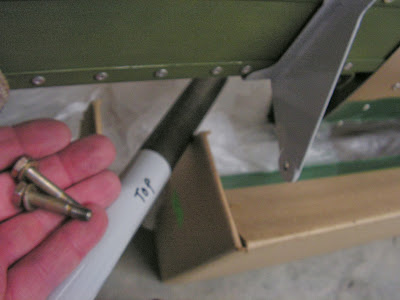
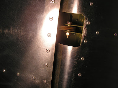
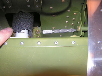
Step 2: Insert the counterbalance into the tailcone by rotating it 90 degrees. Then reinstall the counterbalance arm in it's original position with the hardware called out in the RV-12 plans by Van's Aircraft.
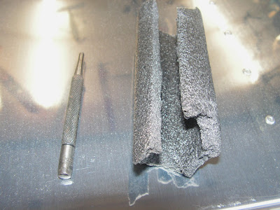
Builder's note: I temporarily put a piece of pipe insulation around the arm to protect it.
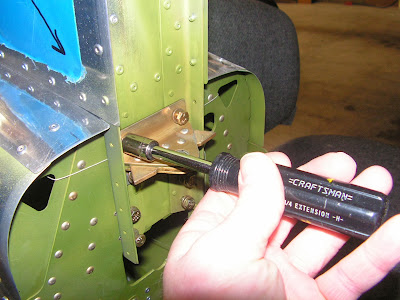
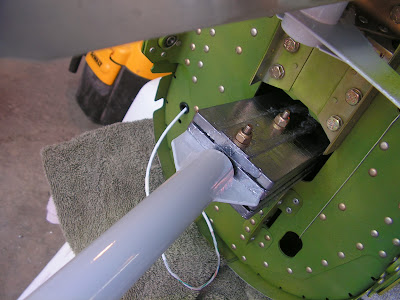
Step 3: Installed the Stabilator assembly using the tool shown above and the hardware called out.
Step 4: Check the travel of the Stabilator. Ensured the travel is only be limited by the hinge stops contacting the hinge brackets.
This completes page 11-03.
Reference: Page 11-04
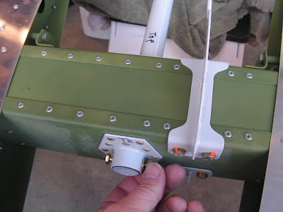
Step 1: Form the two trim tab hinge pins by dulling the point of one end and making a 90 degree bind in the other according to the RV-12 airplane plans.
Step 2: Install both of the trim "AST" Assemblies to the Stabilator using the hinge pins from step 1.
Step 3: Connect the two AST Assemblies together using the hardware called out by Van's Aircraft.
Step 4 on this page deals with safety wiring the hinge pins on the AST tabs. However since I am remove these for painting before flight and final inspection these are being left until later and will be documented at that time. This completes today's work of the RV-12.

