Having decided to install the Dynon Skyview into the RV-12 airplane has made it necessary to complete a number of kit updates so this entry continues these updates. This entry also deals with installing the Skyview ADS-B into the RV-12 aircraft during construction. At this point page 53-02 was completed back on 7/4/13. So we are going to start today with page 53-03.
Step 1: NA Remove Backshell from Magnetometer 9 pin connector and brackets.
Step 2: Curve the SkyView Template to match the curvature of the Top Skin. Make the curve by slide the skyView template back and over the edge of a table.

Step 3: Position the SkyView Template on the Top Skin as shown in figure 1 on page 42D-10 of the RV-12 plans. Match-Drill #30 the holes indicated. Cleco each hole as you drill.

This completes page 42D-10.
Reference: page 42D-11
Step 1: Drill #30 a pilot hole above the upper of the two wire run holes in the lower part of the F-1207-L Baggage Bulkhead Channel. Place the hole above the upper hole the same distance as is in between the lower two holes. Use a step drill to enlarge the #30 hole to 3/8. Insert a SB375-4 snap bushing into the hole.

This completes page 42D-11
Reference: 53-03
Builder's note: The first two steps on this page will be completed earlier.
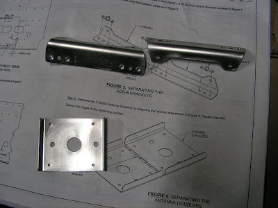
Step 3: Label and separate the SkyView ADS-B Brackets. Deburr the edges of both parts.
Step 4: Machine countersink the nutplate attach holes in the SkyView ADS-B Brackets. Rivet nutplates to the brackets using the hardware called out by Van's Aircraft.

Step 5: Separate the Antenna Doublers. Discard one part. Deburr the remaining doubler.
This completes page 53-03.
Reference: 53-06
Step 1: Remove the hatched area as shown in figure 1 to leave one Guide Bracket.
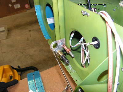
Step 2: Position the Guide Bracket on the inboard flange of the Baggage Bulkhead Channel with the forward edge of the bracket even with the start of the bend in the flange of the channel. See figure 2 on page 53-06. Position the Guide Bracket vertically approximately as shown in figure 2 (exact position is not critical.)

' Step 3: Use a 12" long #30 drill to match-drill #30 both holes in the Guide Bracket into the flange of the Baggage Bulkhead Channel.
Step 4: Remove the Guide Bracket. Deburr the holes in the bracket and channel.
Step 5: Rivet Guide Bracket to the Baggage Bulkhead Channel.

Step 6: Route the ADs_B Antenna Cable through the hole in the bracket. Make a slit in the snap bushing, wrap it around the ADS-B antenna cable, and insert in the guide bracket.

This completes page 53-06.
Reference: 53-07
Step 1: Position the F-00020 Antenna Doubler on the F-1282-L Bottom Left Skin. Match drill #30 and cleco the four .098 holes in the doubler into the skin. Drill #30 the center of the middle hole. Final-Drill 9/16 the center hole in the skin. Remove the doubler and deburr the holes in both the doubler and skin.

Step 2: Rivet the Antenna Doubler to the Bottom Left Skin using LP4-3 rivets, with the factory head on the outer skin.

Step 3: Drill #30 three holes in the web of the F-1208 Fuselage Frame for tie wraps (if not already punched in the part). See figures 2 and 4 of the RV-12 airplane plans on page 53-07. Deburr the three holes.

Steps 4 & 5 on this page deal with mounting the antenna and antenna cable and I will be doing these later in the build. I did check the fit of the antenna at this time as I do not plan to mount it until after painting the airframe. So that is is for this entry.

