Today will all but finish up the installation of the Auto Pilot servos into the RV-12 aircraft. The only remaining thing after today will be log book entires. Since I don't have the log books the entries will have to wait.
Step 1: Insert the bolt that will attach the Pitch Servo Pushrod Assembly to the arm of the IF DYNON AP SV32 Autopilot Servo.

Step 2: Attach the autopilot servo to the F-1215-R Seat Rib and F-1269 Servo Doubler using the hardware called out in Figure 1 and Loctite 242 or equivalent medium thread locker.

Step 3: Connect the Pitch Servo Pushrod Assembly to the tab on the WD-1210 Control Column and the IF DYNON AP SV32 Autopilot Servo arm. See Figure 1 on page 44A-04 of the RV-12 aircraft plans.
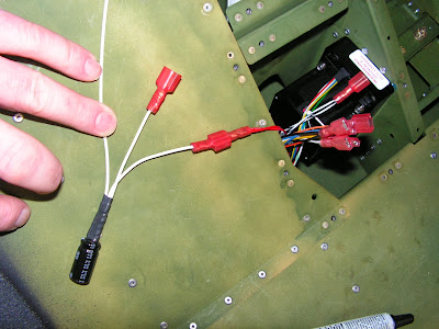
Step 4: Connect the spade terminal on the red wire coming from the Molex connector mating to the IF DYNON AP SV32 Autopilot Servo with the appropriate gender spade connector coming from the ES-00103 Noise Filter. See Figures 2 and 3.
Connect the spade terminal on the red wire coming from the WH-0045 Options Harness to the remaining spade connector on the noise filter.Connect the ring terminal on the noise filter ground wire to the F-1215-R Seat Rib. See Figures 2 and 3.
Step 5: Mate the Molex connector on the IF DYNON AP SV32 Autopilot Servo to the Molex Harness and WH-00046 Fuselage Harness as shown in Figures 1 and 3.
If your aircraft does not have a Molex connector on the autopilot servo wires go to Page 44A-06, Step 4 for instructions to reconfigure your harness to mate to the servo Molex connector. Reference: goto page 44A-06
NOTE: DO NOT cut the male spade connector off the red WH-RV12-OPTIONAL harness and WH-B170 Autopilot Harness wires.
Step 4: Cut the four female spade connectors off the ends of the WH-RV12-OPTIONAL harness wires and WH-B170 Autopilot Harness wires. (Each spade connector is crimped onto two wires. These spade connectors were installed per Page 31-09, Step 8.) Cut the male spade connector off the ORN WH-RV12-OPTIONAL harness and WH-B170 Autopilot Harness wires. Cut the male spade connector off the WHT/BLK WH-RV12-OPTIONAL harness and WH-B170 Autopilot Harness wires.

NOTE: See chapter 5W Open Barrel Crimp.
Step 5: Strip the ends of the twelve WH-RV12-OPTIONAL/WH-B170 Autopilot Harness wires. Twist together the stripped ends of each pair of like colored wire and crimp an ES-00003 Molex Pin, .093" (14-20) onto the end of each wire pair.
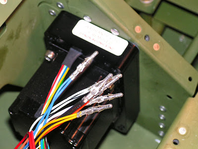
Step 6: Insert the six WH-RV12-OPTIONAL/WH-B170 Autopilot Harness wire pairs into an ES-00010 Molex Plug, 9 Position as shown in Figure 2. Numbers identifying the wire positions are molded into the back of the connector.

Step 7: Cut a piece of 22 gauge wire 3 1/2 inches long. Strip one end and crimp on an ES-00005 Molex Pin, .093" (18-22). Strip the other end and crimp on an ES 421-108 Female Spade Connector.

Step 8: Insert the Molex pin end of the wire into position 6 of the ES-00010 Molex Plug, 9 Position as shown in Figure 2. Continue the installation process by returning to Page 44A-04, Step 6.


This completes page 44A-06.
Reference: Back to page 44A-04.
Step 6: Install a tie-wrap around the IF DYNON AP SV32 Autopilot Servo to secure the Molex connectors and ES-00103 Noise Filter as shown in Figures 1 and 3. Tie-wrap wires as required to prevent wires from chafing.

Step 7: Check controls for full range of motion.
This completes page 44A-04. THis section is all but done. Page 44A-06 deals with installing the autopilot disconnect switch which is already installed in section 42D. It also deals with logbook entries and Pilot Operating Handbook entries that willneed to be done later.

