Today I will start installing the autopilot servo into the RV-12 aircraft. I have to say not having the tailcone in place makes this job much easier as opposed to crawling into the baggage compartment.
Step 1: Cut all the wires coming from both IF DYNON AP SV32 Autopilot Servos to be 7 inches long.
NOTE: See chapter 5W Open Barrel Crimp. For a good example of an open barrel crimp see the WH-00045 Options Harness.
Step 2: Strip the ends of all the wires coming from both IF DYNON AP SV32 Autopilot Servos and crimp an ES-00006 Molex Socket, .093" (18-22) onto the end of each wire.

Step 3: Insert the wires from each IF DYNON AP SV32 Autopilot Servo into an ES-00009 Molex Receptacle, 9 Position (.093" Sockets) as shown in Figure 1 on page 44A-06. Numbers identifying the wire positions are molded into the back of the connector.

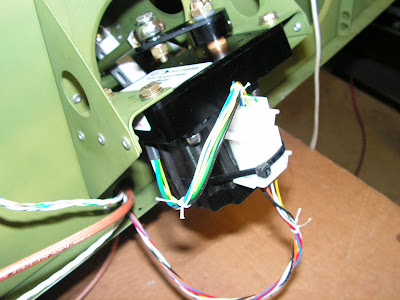
Step 4: Connect the Roll Servo Pushrod Assembly to the IF DYNON AP SV32 Autopilot Servo as shown in Figure 2.

Step 5: Mate the Molex connector on the IF DYNON AP SV32 Autopilot Servo to the Molex connector on the WH-00045 Options Harness as shown in Figure 2.
If your aircraft does not have a Molex connector on the autopilot servo wires go to Page 44A-06, Step 1 for instructions to reconfigure your harness to mate to the servo Molex connector.
Reference 44A-06
Step 1: Cut the spade connectors off the ends of the seven WH-B170 Autopilot Harness wires. (These spade connectors were installed per Page 31-09, Step 11.)
Builder's Note: I hate cutting off perfectly good spade connectors!

NOTE: See chapter 5W Open Barrel Crimp.
Step 2: Strip the ends of the seven WH-B170 Autopilot Harness wires and crimp an ES-00005 Molex Pin, .093" (18-22) onto the end of each wire.

Step 3: Insert the seven WH-B170 Autopilot Harness wires into an ES-00010 Molex Plug, 9 Position as shown in Figure 1. Numbers identifying the wire positions are molded into the back of the connector. Continue the installation process by returning to Page 44A-03, Step 6.

Reference back to page 44A-03
Step 6: Bolt the IF DYNON AP SV32 Autopilot Servo to the F-1286B-L & -R Servo Angles using Loctite 242 or equivalent medium thread locker. See Figure 2.

Step 7: Install a tie-wrap around the IF DYNON AP SV32 Autopilot Servo to secure the Molex connectors as shown in Figure 2.
Step 8: Remove the hardware holding the left Flaperon Pushrod assembly to the WD-1215-L Flaperon Torque Arm.
Step 9: Using new hardware provided, attach the Roll Servo Pushrod Assembly and Flaperon Pushrod Assembly to the WD-1215-L Flaperon Torque Arm. See Figure 2.

Step 10: Reinstall the bolt and nut used to attach the right Flaperon Pushrod Assembly to the WD-1215-R Flaperon Torque Arm for the orientation shown in Figure 2.

This completes today's work on the RV_12. Next time I will continue the instllation of the autopilot servos.

