Wednesday, November 13, 2013

Vans Aircraft RV-12 Airplane Build, Section 42D: Skyview Update (part 4)

Reference: Pages 42D-20, 42D-21; 2.5 hours

Steps 5 & 6 on page 42D-20 are the only steps that apply to my installation of the Dynon SkyView on the RV 12 aircraft project, this is because I had not previously purchased the D180 EFIS kit.

Step 5: Find the WH-RV12-Headset wiring harness routed up through the Panel Base comprised of two four conductor shielded wires WH-RV194 and WH-RZ195. Cut off any connectors leaving as much wire as possible.

Builder's note: It isn't list in the plans but RZ194 is from the pilots side and RZ-195 is for the Co-pilot side. This information was found on one of the Vans Aircraft forums at VansAirforce.com.


Crimp the WHT/BLK shield wire coming from WH-RZ194 and WH-RZ195 into one end of a splice. Find the WH-RZ944 (WHT/BLK) wire coming from the WH-00026 Option Conversion Harness, strip then double this wire over and crimp the doubled wire into the other end of the splice. See figure 2 on page 42D-20 of the RV-12 plans by Van's Aircraft.


Crimp the (WHT/GRN) conductor wire coming from WH-R194 and WH-RZ195 into one end of a splice. FInd the WH-RZ941 (WHT/GRN) wire coming from the option conversion harness, strip then double this wire over and crimp it into the other end of the splice.

Strip the ends of the (WHT/ORG), (WHT) and (WHT/BLU) wires coming from the WH-RZ942(WHT) and WH-RZ943 (WHT) three conductor shielded wires in the option conversion harness. Crimp these wires to the remaining wires coming from the headset wiring harness.


Builder's note: I put heat shrink over the bundle of connectors to keep things clean.


Builder's note: After inserting the wires from the new harness into the WH-00026 OPTION and AUTOPILOT sub-d connectors as shown in figure 2 on page 42D-20 I moved on to step 6.

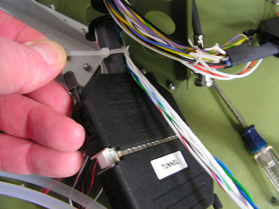
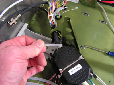
Step 6: Tie-wrap the wires from Step 5 to the wires coming from the backshells at the junction of the WH-00026 Option Conversion harness and the WH-RV12-OPTIONAL.


This completes page 42D-20.

Reference: page 42D-21

Step 1: Find the wires that were routed from the WH-00026 Option Conversion Harness and WH-00036 Tunnel Conversion Harness through the F-1203A Bulkhead.

Step 2: Route the WH-P325 (WHT/RED) wire along the path of the ES RS 279-374 Phone Cable as describled on page 31-03 to the location of the ELT.


That is the last two steps to complete page 42D-21. Next time will be a continuation of the wiring conversion for the Dynon Skyveiw EFIS in the RV12 airplane.

Tuesday, November 12, 2013

Vans Aircraft RV-12 Airplane Build, Section 31: Fuselage wiring (part 12)

Reference: Pages 31-13, 31-15, 42D-19; 2.5 hours

There seems to be light at the end of the tunnel and it is not a train! The Van RV 12 is going well.

Step 6: Make two Wireway Foam Strips from FOAM 1/6X1/4 V1110. Adhere the wireway foam strips to the top edges of the Over Rudder Wireway.


Step 7: Install the Over Rudder Wireway just left of the Inbd Rudder Pedal Block. Do not over tighten the screw!


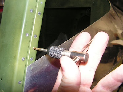
Builder's note: I found using a small screw driver to align the Wireway to be very helpful as pictured above.

Step 8: Remove the two bolts and washers holding the Inbd Rudder Pedal Block halves together. Slide the bolts through the holes in the Wireway Bracket flange then reinstall them. Tie-wrap the main wire bundle to the wireway bracket.


Reference: page 31-15

Step 1: Rivet the F-12122 Artex Elt Bracket to the F-1204F-R Aft Side Bulkhead.


Reference: page 42D-19

Step 1: Attach the WH-00036 Tunnel Conversion Harness to the WH-RV12-TUNNEL harness using ES-00164 D-Sub Backshell Interconnects. Place a drop of blue Loctite on the threads of each thumb screw then fully tighten them into the d-sub backshell interconnects.


Step 2: Attach the WH-00026 Option Conversion Harness to the WH-RV12-OPTIONAL harness using ES-00164 D-Sub Backshell Interconnects. Place a drop of blue Loctite on the threads of each thumb screw then fully tighten them into the d-sub backshell interconnects.

The step above was completed back on October 1st.

Step 3: Tie-Wrap the WH-00036 Tunnel Conversion Harness to the WH-00026 Option Conversion Harness where the wires exit each backshell.


Step 4: Tie a note to the cushioned clamp to tie-wrap the WH-RV12-TUNNEL harness to the wires going through the cushioned clamp near the left ES CPU FAN on either side of the clamp when all wiring has been completed in Section 42C. This will allow the update harnesses to be moved during installation of the SkyView avionics system.

This completes page 42D-19. The last step confused me for sometime. So now that I get it, I going to add a note to the Tunnel harness that says " Tie-wrap the Tunnel harness to each side of the wires going through this cushion clamp." That's it for now.

Monday, November 11, 2013

Vans Aircraft RV-12 Airplane Build, Section 31: Fuselage wiring (part 11)

Reference: Pages 31-14, 42D-18; 3.0 hours

Today is a continuation of the wiring in the Vans Aircraft RV12. Updating to the SkyView EFIS has made the wiring more intersting, bur this is a great ELSA aircraft kit. It nice to see Van's has put so much work and thought into these upgrades.

Step 1: Remove the d-sub backshell from the main 37-pin d-sub connector on the WH-RV12-TUNNEL harness. Insert the RV12-MUSIC harness, WH-P30 Trim Wires and WH-RV12-PTT-P and WH-RV12-PTT-CP Push To Talk Harnesses through the heat shrink and into the correct pin locations on the 37-pin d-sub male connector as shown in Figure 2. Check with a gentle tug that each wire has snapped into place. Slide the heat shrink supplied with the tunnel harness up the wires until its length is centered about the exit of the backshell then activate the heat shrink. Re-install the d-sub backshell.


Reference: page 42D-18

Step 3: Tie-Wrap the WH-RV12-TUNNEL harness to the Aft Pitot Line where the wires exit the backshell on the harness.


Tie-Wrap the WH-RV12-OPTIONAL harness to the WH-RV12-TUNNEL harness where the wires exit the backshell on both harnesses.

Step 4: NA The Over Rudder Wireway has not been installed.

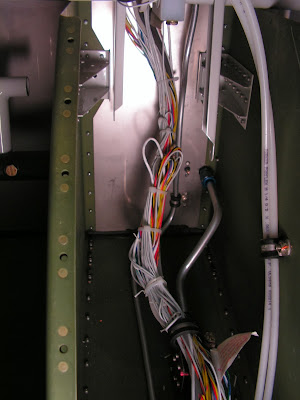
Step 5: Pull the excess from the WH-RV12-TUNNEL and WH-RV12_OPTIONAL wiring harness into the tunnel area. Loooop then tie-wrap the excess wires back on themselves. Use a generous radius six times the diameter of each bundle.


That's it for today.

Sunday, November 10, 2013

Vans Aircraft RV-12 Airplane Build, Section 31: Fuselage wiring (part 10)

Reference: Pages 31-12, 31-13; 3.0 hours

Today I started off with a unhappy discovery on the RV-12 airplane.


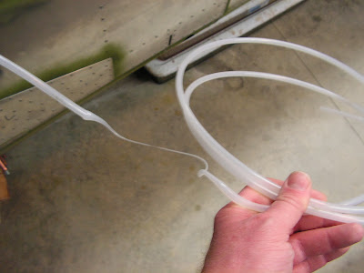
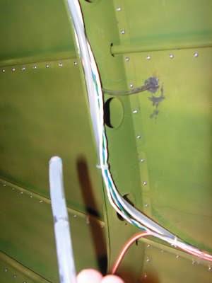
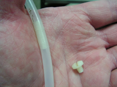
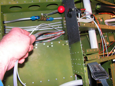
I'm not sure when it melted but above is pictured what is left of my pitot tube. So I decided to replace it all the way from the AHARS unit in the tail up to the firewall. The good news is I will have no splices in it as the updated for the Skyview EFIS system had a splice in the tailcone and at the instrument panel. The update used the old static line that ran from the tail to the panel.


It was much easier to replace than I originally though as I used a 8/32 nyolon bolt to threat the two tubes together and as I pulled the old one out I also pulled the new one in.


Step 1: Route the remaining wires of the WH-RV12-TUNNEL harness back thorough the F-1206A and F-1207B Baggage Bulkheads.

Builder's note: This was completed before I attached the tailcone.

Step 2: Route WH-P30 Trim Wires and Static Line from the tailcone forward through the F-1207B and F-1206A Bulkheads, fuel pump cushioned clamp, F-1204 Center Section Assembly, F-1276C Systems Blocks, F-1203A and F-1202F Bulkheads, fuel flow cushioned clamp, around the back of the rudder pedals and up through the F-1202B Panel Base.


Step 3: NA see section 42D for the update on this step. Route the WH-RV12-OAT harness and WH-RV12-TUNNEL harness through a snap bushing in the F-1207D-L Baggage Bulkhead Channel. Slip the ES HST 3/16 X 2" Heat Shrink over the ends of the wires. Insert the pins on the ends of both wiring harnesses through the heat shrink and into the ES 205203-3 9-Pin D-Sub Female connector according to Figure 2. Check with a gentle tug that each wire has snapped into place. Center the ES HST 3/16 X 2" Heat Shrink around the location where the wires will exit the ES 9 PIN BSHELL. Activate the heat shrink.

Step 4: NA Following the routing of the Static Line, route the harnesses attached to the 9-Pin D-Sub up to the top center of the F-1208 Fuselage Frame, replacing plastic tie wraps as required. br/>
This completes page 31-12.

Reference page 31-13

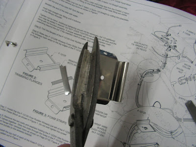
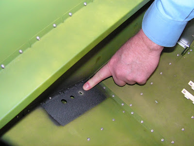
Step 5: Trim the flanges of the Over Rudder Wireway.


This completes today's work. Until next time!

Saturday, November 9, 2013

Vans Aircraft RV-12 Airplane Build, Section 31: Fuselage Wiring (part 9)

Reference: Pages 31-10; 3.0 hours

Another day of installing and updating the wiring in the RV-12 airplane. It is funny but I think this RV-12 has as much wiring running through the plane as my RV-10, however the RV-10 had a lot more wire in the instrument panel. Of course it had a boat load of avionics in the panel!

Step 3: NA Make the WH-B148 (WHT) Power Outlet +V by cutting a piece of 18 gauge wire 84 inches long. Label the wire. Strip one end and crimp on a female spade connector as shown in Figure 1. Install the spade connector to the positive terminal on the back of the ES AS212 12 Volt Power Outlet.

Builder's note: The step above will be replaced with part P350 on page 42D-22. So I didn't install the WH-B148

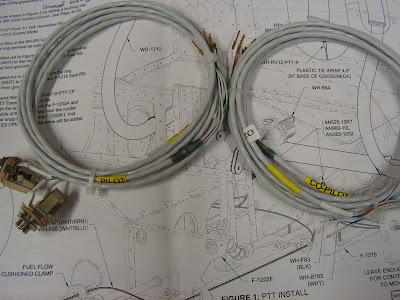
Step 4: Separate the WH-RV-12-HEADSET harness into pilot and co-pilot harnesses. The co-cilot harness is one inch longer.


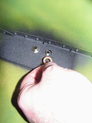
Step 5: Remove the F-1270B ASSY and install the pilot and co-pilot jacks from the WH-RV-12-HEADSET harness into the F-1226-L & -R Seat Ramp Floors.


Builder's note: The insulating washers are only used on the small ID mic jacks while the headphones are grounded against the airframe.

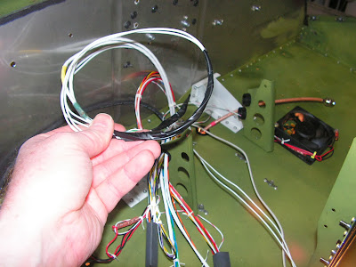
Step 6: Route the pilot and co-pilot harnesses from the WH-RV-12-HEADSET harness inboard through all the F-1215 Seat Ribs.


Step 7: Route the pilot and co-pilot harnesses from the WH-RV-12-HEADSET harness, WH-B148 (WHT) (Builder's note: B148 will be replaced with wire P-350) and WH-RV12-MUSIC harness together forward through the snap bushings in the F-1203A and F-1202F Bulkheads, through the fuel flow cushioned clamp, up the aft side of the firewall, over the rudder pedals, and up through the fwd snap bushing in the F-1202B Panel Base.


Step 8: NA Route the pilot and co-pilot harnesses from the WH-RV-12-HEADSET harness through the snap bushing in the F-1202K-R Inst Stack Support. Label the harnesses pilot and co-pilot. These wires will be hooked up to the intercom in the Avionics Kit.

Builder's note: The step above has been updated with the SkyView system see page 42D-20 step 5.

Step 9: NA see Builder's note above on step 3 Route the WH-B148 (WHT) through the lower snap bushing on the F-1202K-L Inst Stack Support then out through the grommet installed in the F-1201A Firewall Upper on Page 31-03.

Step 10: Route the WH-RV12-MUSIC harness through the lower snap bushing on the F-1202K-L Inst Stack Support and through the cushioned clamp near the left ES CPU FAN. These wires will be connected to the WH-RV12-TUNNEL 37-pin d-sub connector later in this section.


Step 11: na THESE WILL BE INSTALLED IN SECTION 31B Install the F-1270B ASSY per the call-outs on Page 31-2, Figure 5.

NOTE: Audio jack and resistors not provided in kit.

Step 12: If audio output to a video camera is desired add a Ø1/4 hole below the headphone jack with two extra wires coming out (shown on Co-Pilot side in Figure 1). Slip on a long piece of heat shrink over each of these wires then solder a resistor to the end of each. Solder each resistor to separate terminals coming from the back of the audio jack. Slide the heat shrink over the whole assembly then activate the heat shrink. Install the audio jack in the Ø1/4 hole.


Builder's note: I completed this step before installing the co-pilot head phone jacks as I do want a video camera audio jack in the airplane.
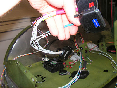
This completes page 31-10 of the RV-12 airplane plan manual.

Thursday, October 3, 2013

Van's Aircraft Introduces new fuel tank gauge for the RV12 airplane

While I was up at Van's Aircraft I noticed that both of the factory RV-12 airplanes had a new fuel gauge system mount on them. This replaced the old sight window in the side of the tank.


The new gauge is not only being offered on the new kits but is also available as a retrofit on existing tanks for around $70 at the time of this posting. Its part number is "12 fuel tank mod". This is a cool addition as now one can tell how full the fuel tank is while filling it up.


Kind of wish I hadn't built my fuel tank. But I think it is worth the extra work. I will make sure to document my experience with the installation.

Tuesday, October 1, 2013

Vans Aircraft RV-12 Airplane Build, Sections 42D: SkyView Update (part 3)

Reference: pages 42D-19; 1.5 hours

I'm starting back into the wiring update for the SkyView EFIS on the RV-12 aircraft.

Step 1: Attach the WH-00036 Tunnel Conversion Harness to the WH-RV12-Tunnel harness using the ES-00164 D-Cub Backshell Interconnects. Place a drop of blue Loctite on the threads of each thumb screw then fully tighten then into the d-sub backshell interconnects.

I actually did this while attaching the tailcone, because I needed some of the wiring for the tailcone before attaching it.

Step 2: Attach the WH-00026 Option Conversion Harness to the WH-RV12-Optional Harness using D-Sub Backshell Interconnects. Place a drop of blue Loctite on the threads of each thumb screw the fully tighten them into the d-sub backshell interconnects.


Step 3 & 4: Deal with adding the cushion clamp and Tie-wrapping the harnesses. I will complete these after all the wires are ran.

Step 5 (lighting kit installed): Find the WH-L435 (YEL/PRP) and WH-L436(YEL/GRN) wires coming from the WH-0026 RV-12 Option Conversion Harness. Dut both wires three inches from the d-sub connector they are attached to. Cover the end of each wire in heat shrink.

Builder's note: I just removed them from the harness.


Step 6: There are several long wires left coming from the WH-00026 Option COnversion Harness and WH-00036 Tunnel Conversion Harness. Route these wires down through a snap bushing in the Panel Base then follow the path of the WH-RV12-TUNNEL harness theough the to the F-1202F Bulkhead. Use the new wire run holes made in this section to route the harness to the aft side of the F-1203A Bulkhead.


That catches the RV-12 up to date. With the weather turning colder I may jump over to the canopy and finish it up before it's too hard to heat the grage up to 70 degrees. So long until next time!

Sunday, September 29, 2013

Vans Aircraft RV-12 Airplane Build, Sections 25: Tailcone Attachment (part 5)

Reference: pages 25-05; 5.0 hours

Step 5: Final-Drill #36 and tap 6-32 all of the match-drilled holes in the Roll Bar Frames.


It nice to see the updated plans now have the Aft window sealed against rain and fuel.But I plan never to get fuel on the window as it will craze or fog.

Saturday, September 28, 2013

Vans Aircraft RV-12 Airplane Build, Sections 25: Tailcone Attachment (part 4)

Reference: pages 25-05; 2.0 hours

With my new pneumatic rivet puller in hand I am ready to finish riveting the tailcone on the RV-12 aircraft.

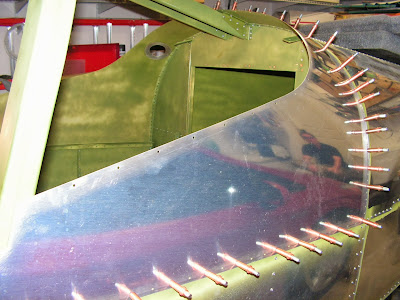
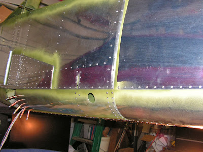
Step 1: Cleco the Fwd Turtle Deck Skins to the Fuselage and Tailcone Assembly.

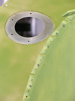
Builder's note: I cleaned the primer off of the skin where the fuel tank filler neck will go as this will need to be sealed with fuel tank sealant.


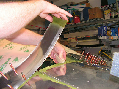
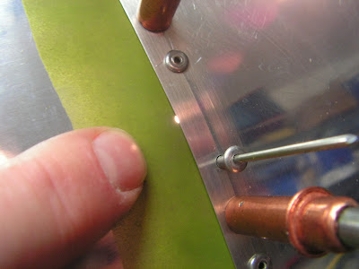
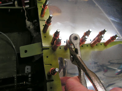
Builder's note: I had some unwanted puckering of the tailcone skins that I am pointing at in the picture above (but you can't really see them." To fix this I pulled the turtle skins back and repent the tabs to remove them.


Step 2: Cleco the Aft Window underneath of the FWD Turtle Deck Skins.


Step 3: Match-Drill #40, beginning at either top inboard holes, the 3/32" holes from the Aft Window into the Roll Bar Frames. Cleco each hole before drilling the next.


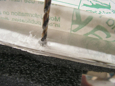
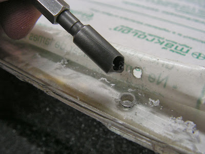
Step 4: Rivet the Fwd Turtle Deck Skins to the Fuselage and Tailcone. Remove the Aft Window. Open all holes in the aft window using a #27 plexi drill bit.
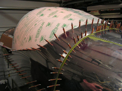


Builder's note: When working with plexi I like to have the room temperature above 70 degree F. At this temperature the plastic is more flexible. Here is a good video on drilling plexi by the EAA and John Monnett:
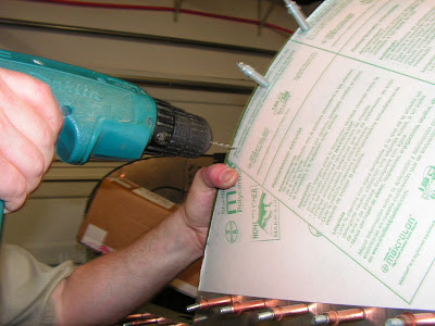


I also drilled the aluminum skins to #27 at this time as well. Also it didn't mention it in the plans but smoothing the edges of the window is very inportant
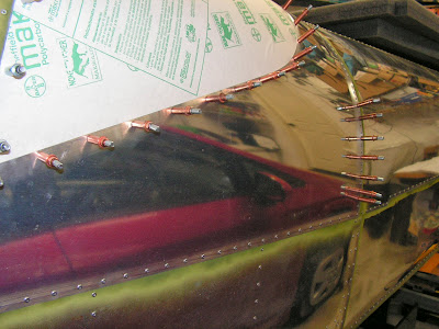

NOTE: Optionally, now is a good time to paint the interior.

Builder's Note: I noticed a number of "holes" at the end of the tab slots that were not covered by the Turtle Deck Skins. I plan to seal these maybe with fuel tank sealant since it is paintable.


Tuesday, September 17, 2013

Vans Aircraft RV-12 Airplane Build, Sections 25: Tailcone Attachment (part 3)

Reference: pages 25-04; 4.5 hours

There has been a new revision (REV 1) to the RV-12 plans for this section which shows the wing fuselage doublers on the sides. I have already added these doublers per the service bulletin.

Step 1: Rivet the F-1284-L & -R Shear Clips to the F-1207C-L & -R Baggage Bulkheads as shown in Figure 1.


Step 2: Cleco the F-1273-L & -R Baggage Corner Skin in place. Underlap the F-1270-L & -R Left and Right Side Skins, F-1270A & F-1270B Side Skin Doublers and F-1276 Bottom Skins. Overlap the Tailcone Assembly skins as shown in Figure 1 and 2.

NOTE: The clecos in the F-1273-L & -R Baggage Corner Skins that are called out in Figure 2 mark holes that will be left open in this section.


Step 3: Rivet the Tailcone Assembly skins, the holes common to the Tailcone and Fuselage Assembly and the F-1273-L & -R Baggage Corner Skins using rivets called out in Figure 2. Rivets on the right side are a mirror of the left.Omit the holes covered by tape. Rivet the holes common to the F-1270-L & -R Skins, F-1280A & F-1270B Side Skin Doublers and F-1273-L & -R Baggage Corner Skins as shown in Figure 2. Remove the tape that was applied earlier in this section.


Today's work period ended abruptly when my Rivet puller died:( It has done a great job through both the RV-10 and RV-12. I tried replacing the seals again but the cylinder was scored and it just leaked fluid all over the place. Oh well until next time.

Monday, September 16, 2013

Vans Aircraft RV-12 Airplane Build, Sections 25: Tailcone Attachment (part 2)

Reference: pages 25-03; 1.5 hours

Well the fuselage of the RV-12 airplane is about to get much longer!

CAUTION: To avoid water penetration, upper skins need to overlap outboard of lower skins and forward skins need to overlap outboard of aft skins.

Step 1: Support the Fuselage and Tailcome Assemblies on saw horses. Bring the Tailcone Assembly to the aft of the Fuselage Assembly. Place the forward edge of the F-1282-L & -R Bottom Skins on the aft edge of the F-1276 Bottom Skin as shown in Figure 1 on page 25-02. Insert the forward edge of the tailcone bottom skins between the F-1207B Baggage Bulkhead and the fuse bottom skin as shown in Figure 4. Cleco the tailcone bottom skins to the fuse bottom skins. Lift the aft end of the tailcone and guide the tailcone skins outboard of the F-1255-L & -R Longerons and inboard of the F-1270-L & -R Fuselage Side Skins. The F-1279-L & -R Upper Skins are outboard of the fuselage side skins, see Page 25-04, Figure 2. Cleco the lower half of the Tailcone Assembly to the Fuselage Assembly in about ten places. Shake the aft end of the Tailcone Assembly up, down, left and right to ensure that the clecoes are set completely.


Step 2: Cleco the F-1207E-L & -R Shoulder Strap Lugs to the inboard surface of the Tailcone Assembly skins as shown in Figure 2.


Step 3: Rivet the F-1207E-L & -R Shoulder Strap Lugs to the Tailcone Assembly skins using rivets called out in Figure 2. Capture the upper flange of the F-1207D-L & -R Baggage Bulkhead Channels when riveting the two forward holes of the shoulder strap lugs.


Step 4: Place masking tape over all of the forward holes in the upper tailcone skins as called out in Figure 3. Taped holes will be riveted later in this section.

That's all the time I had today. Until tomorrow.