Today's log entry will finish up the initial routing and rigging of the Flight Controls on the RV-12 airplane that I am building.
Reference: Page 32-13
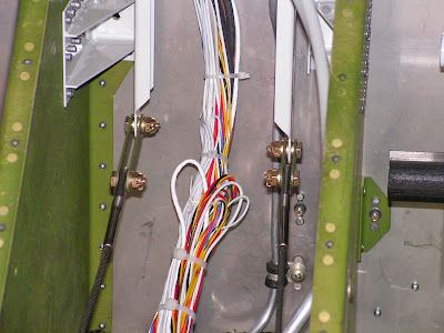
Step 1: Secure the rudder cables using the links that were previously made and the hardware called out by Van's Aircraft.
Builder's note: Unlike other places on the control cables I am not planning to remove these links so they are final installations.
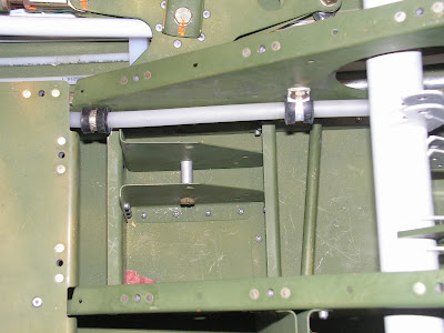
Step 2: Install the bushing in the Pulley Brackets using hardware called out note a MS21083-N3 nut is used.
Step 3: Secure the Stabilator Cables to the Control Column using the hardware called out in the RV-12 airplane plans.

Step 4: Route the cables back over the Bushing and through the Intercostal.
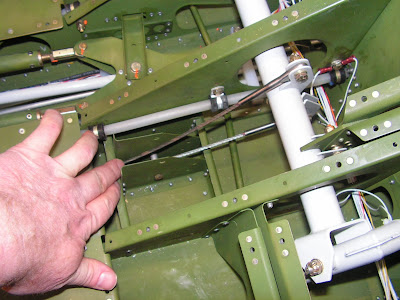
Step 5: Install the two pulleys using the hardware called out by Vans' Aircraft. Ensure the cables are captured between the bushing and the pulleys.
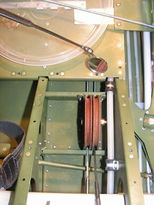
Step 6: Using the strings routed earlier in the build, pull the cables back through the tailcone to the stabilator. Secure the cables with the called out hardware.
Builder's note: I needed to clean the powder coating out of the control horn holes to get the bolts to fit. Also the cotter pins were not final installed because the stabilator will be removed before flight for painting.


This completes page 32-13.
Reference: Page 32-14
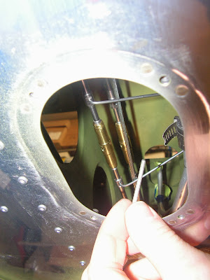
Step 1: Route the Aft Stabilator cables through the holes in the bulkheads. The top Stabilator cable passes through the upper hole.

Step 2: Route the forward Stabilator cables back through the holes in the Bulkhead under the floor. The cable from the right pulley passes through the upper hole.
Builder's note: I found using a Harbor Freight extender very helpful while routing the cables.

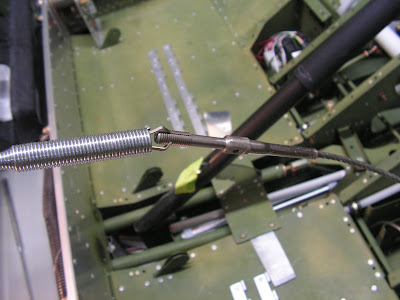
Step 3: From under the airplane, reach through the access hole and connect the Stabilator cables (Aft to Front section). Using a wire tool to hold the end from rotating. Ensure the aft and forward cables start into the barrel at the same time.
Builder's note: My tool is a little different from the on by Van's Aircraft. The pins are bent to the side os as the tool is compressed the pin geometry doesn't change.


NOTE: The seat ramp must be in place while setting the cable tension.
Builder's note: I checked with Van's Aircraft and after the tension is set the seat ramp can be removes. The bulkhead by the control column will flex and lower the tension when it is off.
Step 4: Turn the barrels until a cable tension of 35-45 labs is achieved. Measure this using a cable tensiometer.
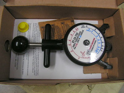
Make sure the stabilator contacts the up and down stops before the Control Column contact its up and down stops. So adjustment maybe necessary to achieve this. Just loosen one turnbuckle and tighten the other cable turnbuckle equal amounts to adjust the travel. Then recheck the tension.
This completes this entry on the RV-12 airplane. The cable barrel locks will be installed after paint during final assembly for flight. Next I will move to installing the tailcone and tail fairings.

