Today works on the routing and installation of the rudder cable on the RV-12 airplane.
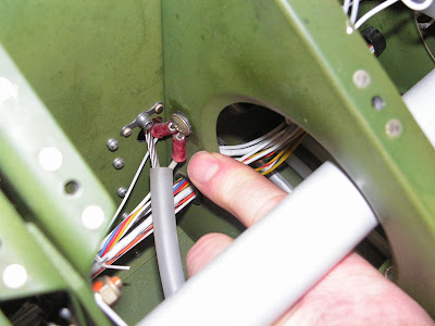
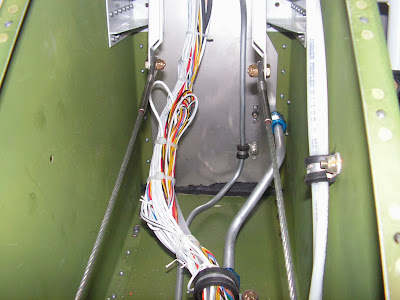
Step 1: Route the spade end of the Rudder cables with the 11.5 inch long plastic sleeve forward through the snap bushings. Locating the sleeves through the 9/16 in holes.
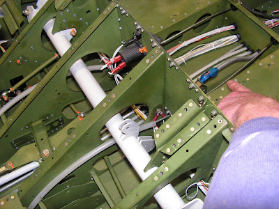
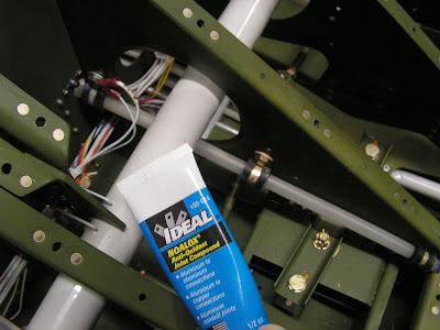
Step 2: Secure the plastic sleeve using the called out hardwares. Builder's note: The electric grounds are already held in place using the holes required for mounting the sleeves. Some builder's have drilled new holes for the grounds, others have used the bolts for mounting the sleeves and used these to also mount the electrical grounds. I went with the latter option and used anticorrosion cream on the hardware.
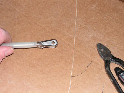
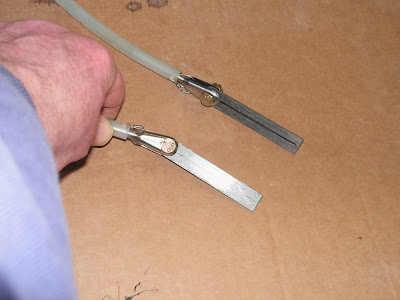
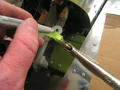
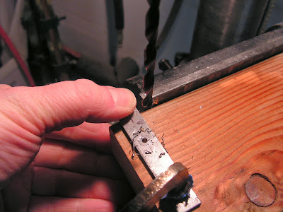
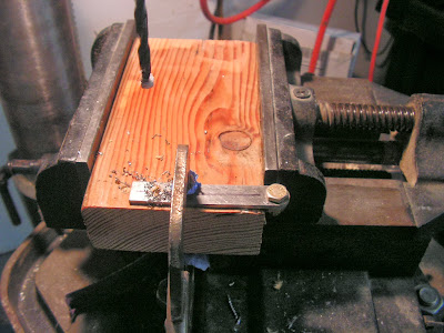
Step 3: Drill #40 hole aprox. 3/16" from the end of the 10 inch long plastic sleeve that goes in the tailcone. NOTE: This is the fork end.
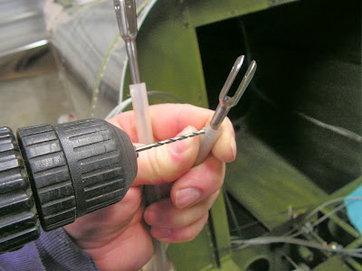
Step 4: Safety wire the 10" sleeves to the fork ends.
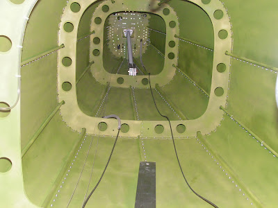
Step 5: Use the strings to rout the rubber cables through the tailcone.
Step 6: Temporarily attach a Rudder Cable Link to each fork end.
Step 7: Temporarily attach the spade ends directly to the Rudder Pedal arms.
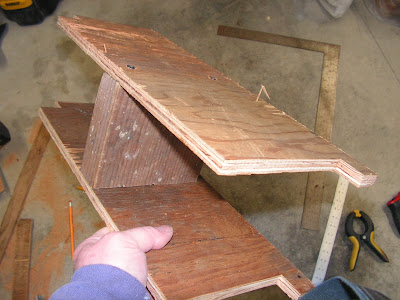
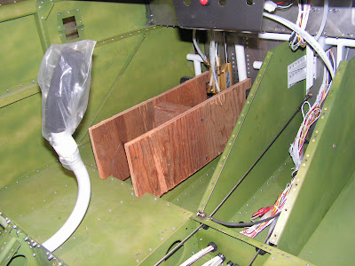
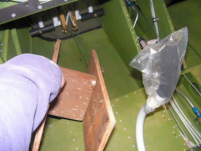
Step 8: Build a Rudder Pedal Rigging Stop out of wood.
This completes page 32-11.
Reference: Page 32-12
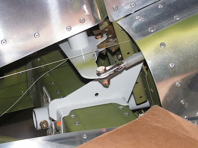
Step 1: Install the Rudder Pedal Rigging.
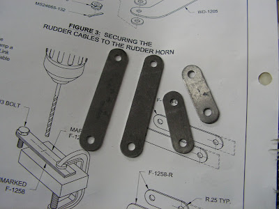
Step 2: Draw a line down the center of the Rudder Calbe Links.
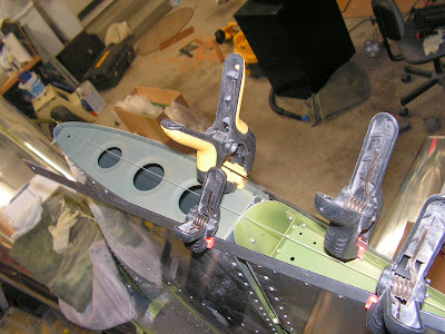
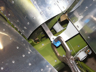
Step 3: Center the rudder and pull the cables tight. While centering the center line through the Rudder Horn holes then clamp them into place.
Step 4: Make sure the Rudder is still centered, then mark the hole centers of the Rudder horns onto the Cable links.
Step 5: Remove the Rudder Pedal Stop Rig.
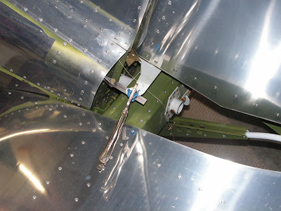
Step 6: Remove the marked Rudder Cable Links and then secure the rudder cables to the Rudder Horn with the called out hardware.
Step 7 & 8: Put a bolt the one of the marked links and one of the unmarked, drill #30, then #12.
Step 9: Repeat on the other set of cable links.
Step 10: Mark and trim the links as show on page 32-12 of the RV-12 plans.
This completes page 32-12.

