After moving the forward fuselage of the RV-12 airplane to the warehouse it is time to finish the fitting of the flight controls to the ailerons. I did have one Gotcha listed below. The length given in the plans for the grommet was too short. I will say not having the tailcone installed made this step much easier.
I also complied with SA 03-17-11 by inspection the flaperon tubes for complete weld. Which my torque tubes did have.
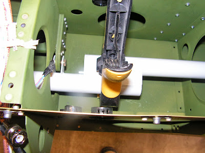
Step 1: From the 12 inch length of MS21266-1N Nylon Grommet supplied, cut two lengths and install them around the edges of the holes in the Baggage Corner Skins.
Builder's note: The 3 3/16" lengths given in the plans were about 1/2 too short for my plan. So I ordered new grommet and fit it around the hole marked and then cut it.
Step 2: Slide the Flaperon Torque Tubes through the holes in the Baggage Corner Skins and between the bracket of the Flaperon Torque Arms.
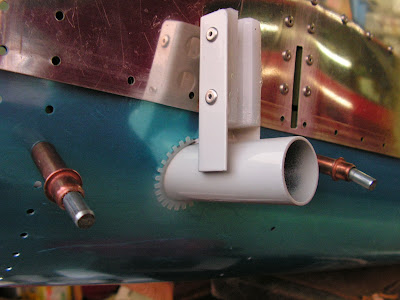
Step 3: Place the WD-1213 Flaperon Handle in the lowest detent in the Flaperon Detent Bracket, then use the bolt shown in figure 2 on page 32-09 of the RV-12 plans to temporarily lock the flaperon control system in the neutral position. Pass the bolt through the holes in both Flaperon Mixer Arms and through the holes in the Flaperon Mixer bellcranks.
Step 4: Install the wings. During installation, slide the Pivot Guides into the Flaperon Torque Tubes and the Actuation Brackets between the Spacers.

This completes page 32-09.
Reference page 32-10
Step 1: On both wings use a clamp to align the flaperon and wing trailing edges.

Step 2: Flush the ends of the Flaperon Torque Tubes with the brackets on the Flaperon Torque Arms as shown in Figure 2 of Van's AIrcraft plans page 32-10. If the Actuation Brackets on the Flaperons force the flaperon torque tubes to extend beyond the brackets, trim the actuation brackets until the flaperon torque tubes are flush.
Step 3: Insert a temporary 0.063 spacer between the Flaperon Torque tubes and the Flaperon Torque Arms as shown in figure 2 on page 32-10, then clamp the parts together.
Step 4: Match-drill #30 to two holes of the Flaperon Torque Arms into the Flaperon Torque Tubes (one side only, and cleco the first hole before match drilling the second.)
That's it for this entry. Next time I will finish drilling the torque arms.

